Probes
On an N1000A, you can connect probes to a module's channel inputs. Due to a wide variety of signals that may be encountered, which range from high bandwidth (fast rise times) to high impedance, one type of probe may be more effective than another type. Therefore, it is helpful to understand the different effects caused by the interaction between the probed circuit and the probe. The response of the probe is part of the overall measurement system response. When a probe is connected to the instrument to measure a signal it becomes part of the circuit under test. The probe can then degrade the circuit under test. The new circuit will behave differently than the circuit without the probe. The following picture displays the probe as part of the circuit under test.

Keysight Probes that are directly supported are listed in the following tables. If your probe is:
- Not a directly supported model but still requires an N1022A/B or N5477A adapter, connect the probe and specify a model number of a similar probe that has the same attenuation factor.
- Not similar to a supported probe or does not use an adapter, define the probe as an external attenuator in the External Hardware Setup dialog.
Directly Supported Probes
Refer to the individual probe documentation for the latest information on product specifications.
Always use the proper connection technique when connecting N2800A-series probes to the oscilloscope.
| Probe | Attenuation Factor |
Bandwidth | ZIn | Dynamic Range | Required Adapter |
|---|---|---|---|---|---|
| N2803A | 6:1 | 30 GHz | 100 KΩ | 2.5 Vp-p | N5477A |
| N2802A | 6:1 | 25 GHz | 100 KΩ | 2.5 Vp-p | |
| N2801A | 6:1 | 20 GHz | 100 KΩ | 2.5 Vp-p | |
| N2800A | 6:1 | 16 GHz | 100 KΩ | 2.5 Vp-p |
| Probe | Attenuation Factor |
Bandwidth | Dynamic Range | DC Offset Range | Input | Required Adapter |
|---|---|---|---|---|---|---|
| 1169A | 3.45:1 | 13 GHz (typical) | ± 3.3 V | ± 16 V | Differential Input R: 50K ohm Differential Input C: 0.21 pF. Single Ended Input R: 25K ohm. Single Ended Input C: 0.35 pF. |
N1022A/B |
| 1168A | 3.45:1 | 10 GHz | 3.3 V pk-pk | ± 16 V | Differential Input R: 50K ohm. Differential Input C: 0.21 pF. Single Ended Input R: 25K ohm. Single Ended Input C: 0.35 pF. |
|
| 1158A | 10:1 | 4 GHz | ± 5V DC | ± 15V DC | ||
| 1157A | 10:1 | 2.5 GHz | ± 5V DC | ± 15V DC | ||
| 1156A | 10:1 | 1.5 GHz | ± 5V DC | ± 15V DC | ||
| 1152A | 10:1 | 2.5 GHz | ||||
| 1134A | 10:1 | 7 GHz | ± 2.5 Vdc | ± 12V | 25 KΩ single mode 50 KΩ differential mode input resistance |
|
| 1132A | 10:1 | 5 GHz | ± 2.5 Vdc | ± 12V | 25 KΩ single mode 50 KΩ differential mode input resistance |
|
| 1131A | 10:1 | 3.5 GHz | ± 2.5 | — | 25 KΩ single mode 50 KΩ differential mode input resistance |
Probe Power Connectors
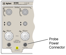
On 54752A, 54754A, 86108A, 86108B, and 86112A modules, a probe power connector, shown in the following figure, allows an N1000A to automatically detect when a probe-power connection to a probe is made. Because information about the attached probe cannot be detected, you must use the External Hardware Setup dialog to enter the probes parameters. When you connect the adapter's power cable to the module's front-panel probe power connector, the Probe Setup dialog is displayed. In this dialog, select the probe that most closely matches the probe you are using.

To connect a probe
The following procedures are provided for connecting probes:
After a probe is connected, perform a Probe calibration.