Resistive Loading Effects
The two major effects caused by resistive loading are amplitude distortion and changes in DC bias conditions in the circuit under test.
Amplitude Distortion
Refer to the following graphic to view amplitude distortion. Note that waveform 1 is the signal before probing and waveform 2 is the signal while probing. The baselines of these signals have been overlayed to show the change in amplitude. If the baseline of a signal is not at zero volts it will shift when the signal is probed.
The cause of the error is the voltage divider developed between the source resistance of the device under test and the input resistance of the probe being used. The following equation calculates the error caused by the voltage divider.
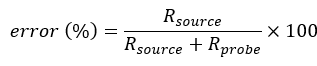
A probe with an input resistance ten times that of the source resistance of the device under test causes a 9.09% error in the measurement. It is best to use a probe with an input resistance at least ten times that of the source resistance.
Bias Changes
Probes with low input resistance can cause bias changes in the device under test. An example of this effect can be seen when probing ECL circuits. The following graphic depicts a typical ECL node with a 60 Ω bias resistor to –2V. I p represents current that flows from ground into the circuit when the probe is connected.
The table shows the current that flows in each device at both the high (–0.8V) and low (–1.75V) states, with and without a 500 Ω probe connected.
| High (–0.8V) | Low (–1.75V) | |||
|---|---|---|---|---|
| Current Path | Without Probe | With Probe | Without Probe | With Probe |
| IO | 20 mA | 18.4 mA | 4.2 mA | 0.7 mA |
| IR | 20 mA | 20 mA | 4.2 mA | 4.2 mA |
| IP | 1.6 mA | 3.5 mA | ||
Probing ECL Circuits
You will notice that in the high state there is little difference in current flow with or without the probe connected. However, in the low state, the output stage is closer to cutoff. In the low state, connecting the probe will source current into the output node. This will reduce the current that is sourced from the gate output. The output current then drops from 4.2 mA to 0.7 mA. This low output current can cause problems with switching noise margins. The output gate will have difficulty reaching the low threshold, causing AC performance to degrade. Be careful not to use a probe just because it has the highest input resistance available. High-resistance probes usually come with tradeoffs in other important parameters, such as higher capacitance, which also affect measurement accuracy.