InfiniiMax III Calibrating
The following procedure calibrates the probe's DC accuracy at a default level of 5.0 mV. Since this is a DC calibration, the probe amplifier's position is not critical, only good physical lead contact is required. Probe calibration identifies the probe's gain and offset and then applies those factors to the calibration of that channel. The N1000A calibrates the voltage at the tip of the probe or the cable input. Because, for active probes (for example, an 1168A), the N1000A can identify the gain and offset factors through the probe power connector and automatically adjust the vertical scale factors for that channel, a probe calibration does not have to be performed, but is recommended. For passive probes or non-identified probes, the N1000A adjusts the vertical scale factors only if a probe calibration is performed.
Use the N5443A Calibration/Deskew Fixture to properly position the probe amplifier during the procedure. If you are using the browser probe head, you can also use the N2787A 3D Probe Positioner, if available, to hold the browser in place. Otherwise, it is possible to gently hand hold the browser on the N5443A. To make calibration easier when using an N5445A browser head, you can optionally remove the plastic holder from the fixture by removing the four screws on the bottom side of the holder. Use a TORX T6 x 60 driver.
Since the following probe calibration only removes offset and gain effects, a high-frequency fixture is not needed. However, any fixture should not introduce any loss between the probe tip and the BNC connector.
Always use a static-safe workstation when connecting or probing with N2800A-series probes.
Procedure
- Click Tools > Calibrations and calibrate the module for the channel where you intend to connect the probe.
- Using the N5477A adapter, connect the probe to a channel input on the oscilloscope.
- Turn on the channel to which the probe is connected.
- Confirm that the 50 ohm terminator (included with N5443A) is connected to the fixture.
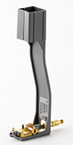
- Holding the N5443A upright, use an adapter to connect the N5443A to the N1000A's DC Cal connector. The following picture shows the browser head probe placed on the fixture using a probe positioner. On the fixture, the center gold trace is the signal and the large plates on either side are both ground as shown below. The positive (+) lead of the probe is connected to the fixture's signal trace and the negative (–) lead to the ground area.
- If you are using a browser head as shown in the picture, remove the fixture's plastic holder from the N5443A.
- If you are using the ZIF probe head or the Solder-in probe head, do not remove the fixture's plastic holder. Instead, insert the probe amplifier into the top of the fixture holder. The amplifier can slide up and down in the holder to adjust the probe head position. Use the fixture's three spring-loaded fingers to clamp the probe head wires to the fixture.
- Click Tools > Calibrations and, in the Calibrations dialog, select the Probes tab.
- Click the Calibrate for the appropriate channel. Wait for the calibration to complete. This particular combination of probe amplifier, probe head, and oscilloscope channel input has been calibrated.
Always use the correct connection technique.
Instead of using the N4553A fixture as described in the following two steps, as an alternative you can connect a cable to the front-panel DC Cal connector and hand probe the end of the cable. The positive (+) probe lead should be connected to the cable's center conductor. Skip to step 7.
When connecting the probe head to the fixture, do not press down with much force or you could snap off the fixture from the Cal Out connection. Light contact is all that is needed for the calibration.
Never solder a probe tip to the thickfilm gold. The gold will immediately dissolve into the solder and disappear.
When used on an N1000A oscilloscope, the probe amplifier's DC Cal LED will not turn green. This does not indicate a problem with the calibration or probe amplifier.