Reference Rx
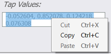
Copy Tap Values
For the linear and non-linear equalizers, you can copy and paste the displayed tap values using Windows clipboard by right-clicking on selected taps or using Ctrl-A, Ctrl-C, and Ctrl-V
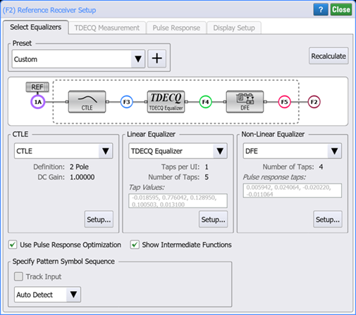
 The Reference Rx (Receiver) operator allows you to create a reference receiver for use when testing transmitters. After dragging the Reference Rx to the Waveform Signal Processing Setup window, click on the Reference Rx operator to open the setup dialog as shown in the following figure.
The dialog allows you to cascade a CTLE equalizer, Linear Equalizer (FFE, or TDECQ), and a Non-Linear Equalizer (DFE) intermediate operators. For the Linear Equalizer intermediate function, you can select either Linear Equalizer or TDECQ Equalizer. You are not required to assign all three equalizer blocks. When you click on a intermediate operator block (or click Setup), the setup dialog for the associated equalizer is opened.
After installing the Reference Rx operator in the Waveform Signal Processing Setup dialog, always immediately connect the input waveform to the Reference Rx operator's input. This is especially needed if you include a TDECQ intermediate operator. Because FlexDCA detects the signal type (NRZ or PAM4), FlexDCA can configure the TDECQ intermediate operator's setup dialog with the correct Measurement tab and available presets. If you simply want to view these settings but a waveform is not available, you can easily install a simulated module to provide a suitable waveform.
Presets
The Equalizer Preset and TDECQ Measurement Preset (for PAM4) or TDEC Measurement Preset (for NRZ) are located at the top of the dialog, configure a Reference Receiver to settings called out in various standards. The TDECQ Measurement Preset and TDEC Measurement Preset are global variables in FlexDCA and are displayed in the applicable dialogs. You may have noticed them shown in the Configure Measurements and PAM Analysis Setup dialogs.
Depending on the signal type (NRZ or PAM4), the dialog's presets, and Measurement tab (TDECQ or TDEC) will be different.
Dialog for PAM4 Signal
Ref. Rx Equalizer Presets
|
TDECQ Measurement Presets
|
Dialog for NRZ Signal
TDECQ Equalizer Presets
|
TDEC Measurement Presets
|
Advantages of Reference Rx
- Reference Rx is the only way to perform joint FFE and DFE optimization in FlexDCA. If the equalizers are chained together outside of the Reference Rx operator, they will not be jointly optimized.
- Reference Rx makes it easier to define points in the system which can be selected as the reference point for TDECQ measurements (where the reference OMA is measured and noise is conceptually added for TDECQ measurements).
- Reference Rx groups all the reference receiver settings in one place.
- Reference Rx allows presets to define an entire reference receiver configuration that involves multiple equalizers.
The dialog's Pulse Response tab is displayed whenever the dialog's Use Pulse Response Optimization setting is selected.
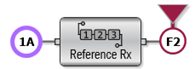
Default Configuration Upon Installation
When the operator is first installed on the Waveform Signal Processing dialog, the following defaults exist as shown in this picture. The Show Intermediate Functions setting is off. Also, the first intermediate function (CTLE) is not loaded, but the TDECQ and DFE intermediate functions are loaded. In this situation, because Function numbers are not assigned to the secondary functions, no inner waveforms can be displayed. To assign function number, turn the Show Intermediate Functions setting on.

Assigned Function Numbers
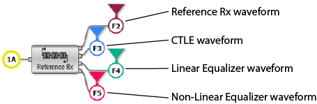
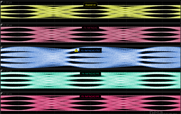
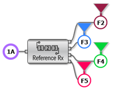
The following diagram shows the Reference Rx operator with its associated waveforms. On the Waveform Signal Processing Setup window, the Reference Rx operator's assigned function number automatically determines function numbers of the secondary operators. For example, in the figure the Reference Rx operator's function number is F2 and its secondary functions are:
- CTLE: F3
- Linear Equalizer:F4
- DFB Equalizer: F5
When identifying waveforms and sending remote SCPI commands, be sure to use the correct function numbers.
![]() The yellow advisory symbol is displayed if a problem exists with an equalizer's setup. Click on the symbol to learn about the advisory.
The yellow advisory symbol is displayed if a problem exists with an equalizer's setup. Click on the symbol to learn about the advisory.
![]() The red invalid symbol is displayed if the current settings result in an invalid status. Click on the symbol to learn about the problem. This can occur when Automatic Taps is on, and the tap optimizer can not find a solution. Your pattern might not have sufficient variation in symbol sequences, such as a clock signal. Or, that the section of your pattern you are currently acquiring does not have sufficient symbol variation. Consider using a pattern with good symbol variation, such as a PRBS, and optimizing the taps over a large span of the pattern. Turn Pattern Lock on and select Acquire Entire Pattern.
The red invalid symbol is displayed if the current settings result in an invalid status. Click on the symbol to learn about the problem. This can occur when Automatic Taps is on, and the tap optimizer can not find a solution. Your pattern might not have sufficient variation in symbol sequences, such as a clock signal. Or, that the section of your pattern you are currently acquiring does not have sufficient symbol variation. Consider using a pattern with good symbol variation, such as a PRBS, and optimizing the taps over a large span of the pattern. Turn Pattern Lock on and select Acquire Entire Pattern.
Show Intermediate Functions
Use the Show Intermediate Functions setting to show or hide the operator's intermediate functions. This setting is persistent, is not saved in a function preset, and has a default setting of on. When the setting is turned off:
- Existing intermediate function numbers are removed. For new instances of the operator, the function numbers are not assigned until the setting is turned on.
- Intermediate Function waveforms cannot be displayed.
- The TDECQ Reference Point can still be placed on the reference points. Refer to the following section for information on reference points.
- The output of the Reference Rx operator is not affected.
| ON | OFF (Default Setting) |
|---|---|
|
|
TDECQ Reference Point
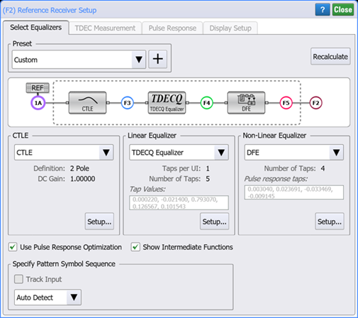
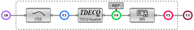
![]() In the dialog, the REF symbol identifies the reference point. The reference point changes the information used to measure TDECQ on the output signal. The OMA value used in calculating TDECQ is made at the reference point and the noise gain is calculated between the reference point and the output of the operator. By default, the reference point is set at the Reference Rx operator's input waveform. You can drag the reference point to the output of any secondary function. For example, from 1A to F4 as seen in the following figure.
In the dialog, the REF symbol identifies the reference point. The reference point changes the information used to measure TDECQ on the output signal. The OMA value used in calculating TDECQ is made at the reference point and the noise gain is calculated between the reference point and the output of the operator. By default, the reference point is set at the Reference Rx operator's input waveform. You can drag the reference point to the output of any secondary function. For example, from 1A to F4 as seen in the following figure.
Automatic Taps
 The Linear (FFE or TDECQ) and DFE operators include taps which can be automatically set (default) or manually entered. The taps setting is not linked and can be different for each operator. Click Recalculate and, if any of these operators has Automatic Taps selected, its tap values will be recalculated. The calculation will take a few moments to complete.
The taps setting are configured in the secondary operator's Setup dialog.
Aliased Noise Processing
Aliased noise processing is a filter that is applied to the power spectrum of the noise to calculate the appropriate magnitude of the noise on the output. The availability of the aliased noise processing options is based on the type Linear Equalizer selected:
- If a TDECQ Equalizer is selected, the Receiver Rx operator forces the use of Process Spectrum noise processing and you do not need to make a selection.
- If a Linear Equalizer (FFE) is selected, you can select noise processing to be either:
- Process Spectrum. By default, the Input Noise Bandwidth tracks the input response. In the secondary operator, you can manually set the bandwidth. This setting is linked between the CTLE, Linear and TDECQ secondary operators.
- Preserve RMS.
- Turn off noise processing.
The aliased noise processing and equalizer bandwidth settings are configured in the secondary operator's Setup dialog.
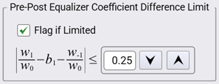
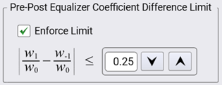
Pre-Post Equalizer Coefficient Difference Limit
The Pre-Post Equalizer Coefficient Difference Limit is called out in the IEEE 802.3dj 2.2/2.3 standard. As shown in the following two images, the field's settings and algorithm differ depending on whether a DFB secondary operator is installed. However, both situations have the same settings limits. The default limit is 0.25, the maximum limit is 1.00 and the minimum limit is 0.100.
When remotely configuring the Reference Rx (Receiver) operator, the Flag if Limited and Enforce Limit settings are set using the same remote command: :SPRocess:RRX:LIMits:BALance:STATe. The limit value is entered using the :SPRocess:RRX:LIMits:BALance:LIMit command.
| Field is Affected by Secondary DFB Operator | |
|---|---|
| DFB Installed (compliant with specification) |
DFB Not Installed (not compliant with specification) |
|
|
The DFE equalizer does not offer Aliased Noise Processing.
The Reference Rx operator requires a single-valued waveform, as opposed to an eye diagram. Be sure that your trigger setup results in a single-valued waveform at the input to this operator. This can be achieved using an external pattern trigger or by using pattern lock. If you are using an external pattern trigger, you may ignore this note.
If an additional CTLE, Linear Equalizer, or TDECQ Equalizer is placed on the Waveform Signal Processing window independent of the Reference Rx, its aliased noise processing setting are independent of the any settings made within the Reference Rx operator.
The Reference RX operator requires FlexDCA revision A.07.80 and above.