Random Operator
 Use the Random operator to add random noise or jitter to a simulated waveform. One operator Preset is provided: IEEE 802.3ck Draft 1.2.
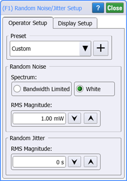
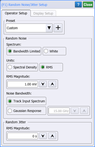
The following two pictures show how the dialog's Operator Setup tab differs depending on the type of noise selected: White or Bandwidth Limited. You can specify the magnitude of the noise. When Bandwidth Limited noise selected, you can additionally:
- Enter the Spectral Density (η0) of the noise (V2/GHz or W2/GHz).
- Select the Noise Bandwidth to Track Input Spectrum or have a Gaussian Response.
The RMS Magnitude of the Random Jitter can be specified.
| With White Noise Selected | With Bandwidth Limited Noise Selected |
|---|---|
|
|
Random Operator Presets
- IEEE 802.3ck
Noise Processing
White Noise
When white noise is selected, an independent Gaussian-distributed random value is added to each sample in the waveform. The magnitude of the noise is specified as an RMS value in the units of the input signal. This noise appears on the waveform the same way that signal noise would appear on an equivalent-time waveform. As shown in the following FlexDCA Waveform Processing figure, the intrinsic noise will not be modified by the random operator. Therefore, any measurement that backs out the intrinsic noise of the instrument will not back out any noise added by the operator. In addition, the noise power spectrum will not be modified. Therefore, any following filter operations will treat this noise as if it has the same power spectrum as the noise on the input (typically the channel bandwidth).
Bandwidth Limited, RMS Defined
When Bandwidth Limited noise in the dialog is selected, the magnitude of the noise may be specified either as a total RMS value (RMS selection) or as a power-per-frequency (η0), the Spectral Density selection. The difference between white noise and bandwidth-limited noise is illustrated in the following figure. While both noise sequences shown in the figure have the same RMS value, the bandwidth limited sequence has a degree of correlation between the samples. This is non-aliased noise like you would measure if a real-time oscilloscope were used to capture the noise sequence.
The default behavior for bandwidth limited noise is to make the noise spectrum track the input spectrum. So, if the input to the operator is a channel with SIRC active and a 4th order Butterworth response, then the noise added will also have a 4th order Butterworth response. If the input is a CTLE with 6 dB of gain, then the noise will match the same 6 dB CTLE response. Just like in the white noise case, in this situation the intrinsic noise and the noise power spectrum will not be modified.
The noise bandwidth can alternatively be specified as a Gaussian response. In this case, the noise will have the specified bandwidth with a Gaussian roll off and the noise power spectrum of the output signal will be correspondingly modified.
Bandwidth Limited, Spectral Density Defined
The per-frequency spectral designation of bandwidth-limited noise is useful when modeling real receivers where the noise power scales with the bandwidth. It is also used to specify reference noise by some standards such as IEEE 802.3ck. When defining noise using the Spectral Density designation, an approximation of the RMS magnitude of the noise can be made as  where f is the noise bandwidth. However, this is just an approximation as the actual value will depend on the shape of the input response (for example, Bessel versus Butterworth versus Brick Wall).
This method of specification has the interesting property that in many cases it doesn’t matter whether the noise is added before or after a filtering operation. For example, imagine that band-limited noise is added to a 40 GHz channel and then filtered with a 10 GHz filter. The RMS magnitude of the noise added will be approximately  . After applying the 10 GHz filter, the RMS noise will be filtered and reduced by a factor of 2 yielding an RMS value of
  . But this is the same magnitude of noise that would have been added if the noise had been added after the 10 GHz filter:
  .
.
Although in that example it does not matter, there are situations where order does matter. For example, consider a simple gain block that doubles the signal. If the noise block is added before the gain block, the noise magnitude will also be doubled by the gain block while it would not be doubled if the noise block is instead placed after the gain block. In most situations, it is best to add the noise as early as possible in the signal processing chain to avoid any ambiguities that otherwise may arise from differential operators, non-linear operators, or filters that do not have unity DC gain.
Random Jitter
As of FlexDCA version 6.60, only jitter with white spectral properties can be added to a waveform.
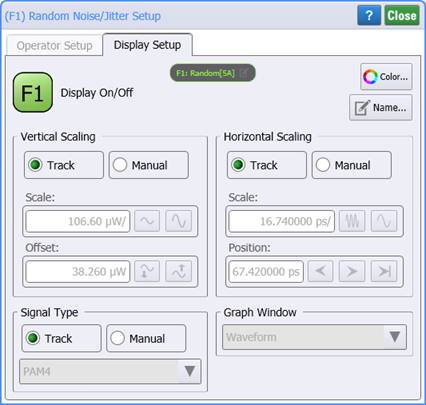
Display Setup Tab
Use the Display Setup tab to control the display of the function's output waveform, including turning the display On or Off. Use the Name field to display an identifying name to the waveform which can be helpful for screen captures or when multiple waveforms are displayed.
To Configure the Operator
- Drag the operator into the construction area.
- Click on the operator to open the Random Noise/Jitter Setup dialog.
- Enter the amount of jitter or noise to be added to the waveform.
- Close the dialog.
The operator's Display Setup configures the manner in which the resulting waveform is displayed including both vertical and horizontal scaling. Track selection to allows the output waveform to track changes to the scaling of the input waveform. Track is the default setting. In addition, you can turn the waveform's display off or on and select the color of the trace.
Use the Name button to give the displayed waveform a custom identifying name which is show in the Signals area on the display graticule and in the Signals palette. Custom names are very helpful for screen captures or when multiple waveforms are displayed.
The Graph Window is available when multiple waveform content windows are used.
Use the Signal Type's Track selection to allows the waveform type (NRZ or PAM4) to track the input waveform's type. Track is the default setting. If input waveform's type cannot be automatically determined, select Manual to specify the waveform type.