Remove S2P Operator
 Use the Remove S2P function to remove the effects of a two-port element from your measurements. This operator is easier to set up than the DeEmbedding operator, however the measurement accuracy is reduced. Before you can use this operator, you must create an S-parameter file of the device to be removed. Import 2-port S-Parameter file into this operator (filename extension of .s2p).
The Deconvolution Setup dialog has several options to compensate for noise effects as well.
Options
Use the Filter field to select a Gaussian Filter, Sinc Filter, or None for no filtering.
If needed, use the Bandwidth field to minimize effects caused by noise that occurs above the frequency where the signal is mostly attenuated. Normally the FlexDCA automatically sets the bandwidth limit. Or, manually enter a bandwidth from 10 MHz to 1 THz with a default value of 7.5 GHz.
You can set the operators Maximum Gain in the range of 0 dB to 100 dB. The default value is 20 dB.
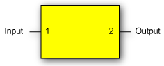
Select the Flip S-parameters field to compensate for reversed port numbering in the file. That is, select this option if the file's S-parameter data is not defined with the ports located as shown in the following diagram. This ensures that the S-parameter order is properly interpreted.
If a 4-port S-parameter file is loaded, additional 4 Port Numbering and 2 Port Extraction selections are added as explained in the following section, Extracting 2-Port Data from a 4-Port S-Parameter File.
Clear the Align Input and Output Waveforms field to view the delay introduced by your device. By default, this field is normally selected and the input and output waveforms are aligned.
Extracting 2-Port Data from a 4-Port S-Parameter File
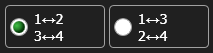
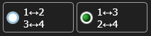
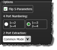 It is possible to import data from a 4-port S-parameter file (.s4p). After you open a 4-port S-parameter file, two additional dialog fields appear that configure how 2-port information is extracted from the file. These fields are 4 Port Numbering and 2 Port Extraction and they are shown in this figure. In the following table, locate the illustration in the first column that matches how the ports are numbered in your device and the corresponding S-Parameter file. The columns in the row show the settings required to properly extract and interpret the required 2-port information.
| Port Configuration in s4p File | 4 Port Numbering Options |
2 Port Extraction Options |
Flip S-Parameters |
|---|---|---|---|
|
|
Differential Common Mode Ports 1⇔2 Ports 3⇔4 |
|
|
|
Differential Common Mode Ports 1⇔3 Ports 2⇔4 |
|
|
|
Differential Common Mode Ports 1⇔2 Ports 3⇔4 |

|
|
|
Differential Common Mode Ports 1⇔3 Ports 2⇔4 |
|
Noise Processing
None Selection
The option
Process Spectrum Selection
The option
The default behavior of the Process Spectrum noise processing option is to use the noise power spectrum of the input signal. If the input signal is a sampling scope channel with SIRC active, this spectrum will be established by the measured hardware response of the channel. For other channels, the response will be assumed Gaussian with a 3 dB frequency corresponding to the nominal channel bandwidth. This behavior can be overridden by clearing the Track Input Response checkbox and manually entering a bandwidth. If this option is utilized the response will be presumed Gaussian with the selected 3 dB bandwidth.
Preserve RMS Selection
The option
By tracking the accumulated effects of the filtering operations, accurate noise processing can be done even when chaining operations as illustrated in the following figure. In addition to the sampled waveform, information about the acquisition channel and noise power spectrum are maintained in each signal and appropriately processed by each filter. The complete set of auxiliary information is also included when storing FlexDCA waveforms in the *.wfmx file format.
The noise processing feature was added in FlexDCA version A.06.60 and above.
The Remove S2P operator is not available in TDR/TDT mode.
This operator requires a single-valued waveform, as opposed to an eye diagram. Be sure that your trigger setup results in a single-valued waveform at the input to this operator. This can be acheived using an external pattern trigger or by using pattern lock. If you are using an external pattern trigger, you may ignore this note.
The convolution process used by this operator requires that the measurement circuit and the simulation circuit be linear and time-invariant (small-signal analysis requirements).
Jitter measurements can be made on the Remove S2P operator's output waveform.
To Configure the Operator
- Drag the operator into the construction area.
- Click on the operator to open the Deconvolution Setup dialog. The dialog's message prompts you to open a 2-port S-parameter file for your device. You can also open a 4-port device, although the required dialog options are more entailed..
- Click Browse to locate the S-parameter file for your device.
- Set the options as described at the beginning of this topic.
- Close the dialog.
The operator's Display Setup configures the manner in which the resulting waveform is displayed including both vertical and horizontal scaling. Track selection to allows the output waveform to track changes to the scaling of the input waveform. Track is the default setting. In addition, you can turn the waveform's display off or on and select the color of the trace.
Use the Name button to give the displayed waveform a custom identifying name which is show in the Signals area on the display graticule and in the Signals palette. Custom names are very helpful for screen captures or when multiple waveforms are displayed.
The Graph Window is available when multiple waveform content windows are used.
Use the Signal Type's Track selection to allows the waveform type (NRZ or PAM4) to track the input waveform's type. Track is the default setting. If input waveform's type cannot be automatically determined, select Manual to specify the waveform type.