Common Display Settings
This topic explains how to configure your operators. Each operator has its own setup dialog to configure common display settings. To display the dialog, simple drag the operator into the math pallet and click on the operator. Simple operators have a Display Setup dialog with settings used to display the waveform.
More complex operators, like the TDECQ operator, require a Setup dialog that includes multiple configuration tabs and a Display tab. The Display tab includes the settings normally found in a Display Setup dialog.
Example of a Display Setup dialog for an Add Operator
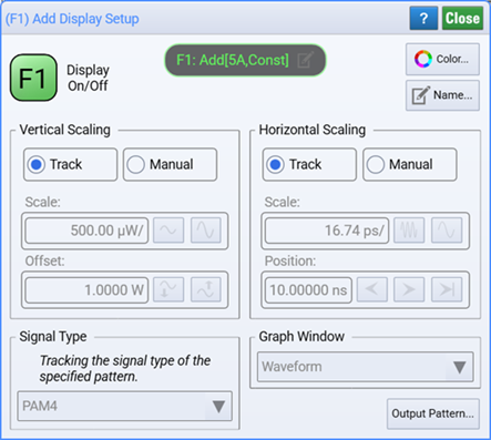
Example of a Setup dialog with Display Setup tab

Display Settings
Click the Display On/Off button to toggle the display of the function's waveform on and off. A gray button indicates that the waveform is not displayed. When displyed, the color of the Display On/Off button matches the color of the waveform.
Vertical and Horizontal Scale
Select Track or Manual for Vertical Scaling and Horizontal Scaling. With Track, the function's output waveform is appropriately scaled and offset based on the scale and offset of the input waveforms. Function scaling tracks any changes to the source scaling. With Manual, changes are no longer tracked and you can independently scale, offset, and position the function's output waveform. Some functions do not allow all of the scaling options shown in the above picture of the dialog. The correct units are displayed for the function.
If the application cannot resolve a particular combination of units, it will display U/div meaning unknown units per division.
Signal Type
Signals can be one of three signal types: Unspecified, NRZ format, or PAM4 format. The PAM4 selection is only available if options 9FP or 9TP PAM-N Analysis software license is installed. Select Track to have a function's output signal type track the function's input signal types. Unlike channel, common mode, and differential waveforms, a function's output signal type is not detected but instead tracks the input signal types. If an input signal type changes, the function's signal type tracks. Consider the examples of signal tracking in the following table. The Add function is shown simply to show a dual-input function. Track is the default setting.
| Example | Input Signal Types | Example Function | Output Signal Type |
|---|---|---|---|
| 1 | Input 1: PAM4 Input 2: PAM4 |

|
PAM4 |
| 2 | Input 1: PAM4 Input 2: NRZ |
Unspecified | |
| 3 | Input 1: NRZ Input 2: constant |
NRZ |
When tracking is set to Manual, the function's output signal type no longer tracks the inputs. Instead, you specify the function's output signal type in the drop-down list.
The Signal Type settings are coupled to the identical settings that are in the PAM-N Analysis Setup dialog. You can make these selections in either location.
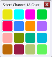
 Click the Color button to display the waveform in one of 16 colors.
 Waveforms displayed in tiled, stacked, or zoom tiled views include a waveform label. You can change the waveform's labels to your own more meaningful user name by clicking the Name button or by clicking the
 icon that appears in the waveform label at the top of this dialog.
 Click Pattern to open the Channel Pattern Symbol Sequence dialog where you can select global information about the pattern on the specified channel. You can select to have the pattern automatically detected, select from known patterns, or enter the name of a custom pattern file. These settings are global for a given source and are used by all Waveform Signal Processing operators. If the source pattern is from a channel, you may see an informational dialog instructing you to click the operator's Advanced tab to access Pattern Symbol Sequence settings.