Excess Capacitance, Excess Inductance

Excess Capacitance measures the excess capacitive reactance on a portion of the TDR waveform as shown in the following figure. The response area over which the capacitance is to be measured must first be placed within a measurement region. This measurement does not work over the entire display.

Excess Inductance measures the excess inductive reactance on a portion of the TDR waveform as shown in the following figure. The response area over which the inductance is to be measured must first be placed within a measurement region. This measurement does not work over the entire display.
Both measurements can be performed on any waveform that is displayed in one of the following content windows:
- Waveform
- Time-Ohms
- Time-Volts
- Time-%
The following picture shows an example of shunt capacitance followed by series inductance on a TDR T11 waveform. The shunt capacitance is measured over measurement region 1 (R1) and the series inductance is measured over measurement region 2 (R2).
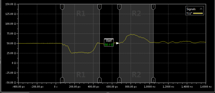
Shunt capacitance is negative going. Series inductance is positive going.
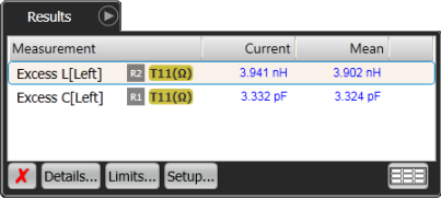
Excess Reactance Measurements in Results Tab
When measuring discontinuities on lines whose impedance is not 50Ω, the excess reactance measurement is still valid as long as the 50Ω measurement system is connected to the non 50Ω line without using matching resistors.
To Measure Excess Reactance
- Click Measure > Measurement Regions. In the Measurement Region Setup dialog, select Enable Measurement Regions and select Number of Regions that you want. You can perform a separate measurement over each region.
- Close the dialog. On the display, drag and size the measurement region over the portion of the TDR response that you to measure the reactance.
- On the Amplitude toolbar, click Excess Inductance or Excess Capacitance.
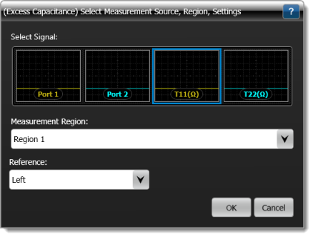
- If multiple signals are shown in the dialog, select the appropriate TDR T-domain response. For example, T11(Ω) or Port 1 (channel).
- In the dialog, select the Measurement Region, if multiple regions are displayed. Select the side of the measurement region to be used as the Reference: Left or Right. Then, click OK.
After Making the Measurement
Once measured, you can compensate for the excess inductance in your design. Excess inductance on high-speed digital DUTs with fast signal speeds results in large impedance discontinuities. These discontinuities can result in higher reflections, signal degradation, and cross talk. Most impedance discontinuities seen on a TDR waveform are a result of series inductance or shunt capacitance:
- Sources of series inductance include very narrow wire bonds or microstrip traces.
- Sources of shunt capacitance include wire-bond pads or microstrip traces that are too wide.
The impedance environment must be controlled to compensate for these imbalances and ensure low reflections and good signal integrity. Excess inductance or capacitance measures the area within the measurement region and calculates the excess reactance by integrating the percent of reflection between the markers. You can relate this excess reactance to the characteristic impedance of your DUT. As noticed in this equation, excess inductance increases Zo, excess capacitance decreases Zo:

SCPI Command
:MEASure:TDR:ECAPacitance
:MEASure:TDR:EINDuctance