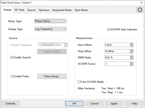
Noise Type - Selects the noise type from the following selections. The Residual Noise requires 2 port hardware configurations.
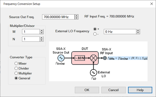
Phase Noise - (Default) - Measures phase noise of a DUT. Select for single channel residual noise measurement when the input and output frequencies of the DUT are not the same. For example, frequency converters.
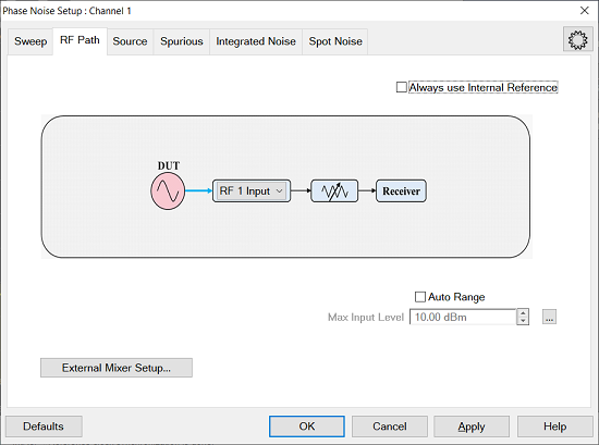
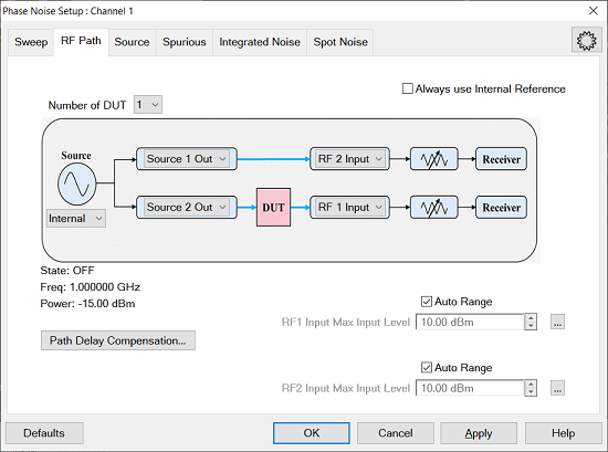
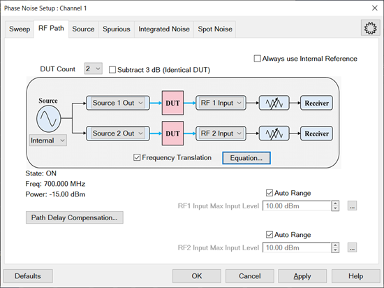
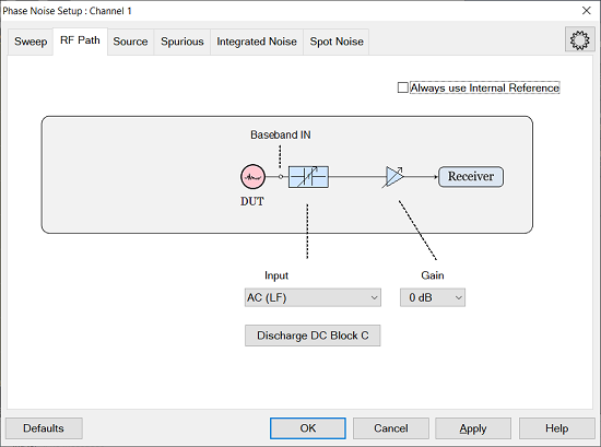
Residual Noise - Measures the additive phase noise of a DUT. This measurement is set up in the RF Path tab using DUT Input and DUT Output. Select for 2-channel residual noise measurement when the input and output frequencies of the DUT are the same. For example, amplifiers. See Residual Measurement.
Baseband - Measures baseband noise.
Sweep Type - Selects from Log Frequency or Segment Sweep.
XCORR Gain Indicator - Enable the Cross Correlation Gain Indicator. The Gain Indicator is a dark area which is located below the measurement trace. It shows the noise floor level which is reduced by the cross correlation technique. Increasing the number of cross correlation reduces this level.
XCORR Counter - Enable the Cross Correlation Counter. This shows the number of current cross correlation averages for each offset frequency segment of Phase Noise.
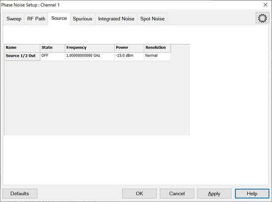
Carrier Frequency - Sets the carrier frequency. The range of the phase noise measurement is determined by the start/stop offset frequency which is relative to the carrier frequency.
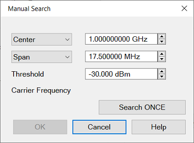
Enable Search - Search the carrier frequency automatically. This feature is not available in Residual and External mixer measurement. When this feature does not work properly or wants to specify the frequency by yourself, disable this feature and click Manual Search...
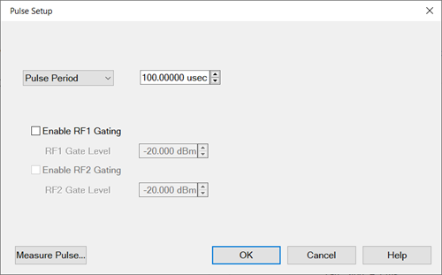
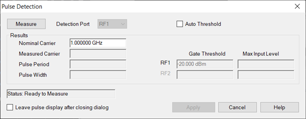
Enable Pulse - This feature is available with S96325B Pulsed-RF measurements for SSA-X Signal Source Analyzer.
Pulse Setup- Show the Pulse Setup dialog.
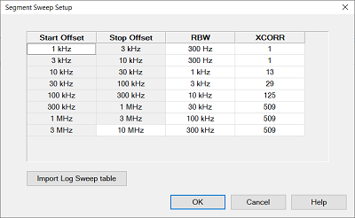
Start Offset - Sets the start frequency of the phase measurement. This is an offset relative to the carrier frequency to position the measurement about the noise sideband to measure power density in dBc/Hz. For example, if the Start Offset is set to 1 MHz with a carrier frequency of 1 GHz, then the dBc/Hz phase noise measurement starts at 1.001 GHz. The minimum frequency is 0.1 Hz.
Stop Offset - Sets the stop frequency of the phase measurement. This is an offset relative to the carrier frequency to position the measurement about the noise sideband to measure power density in dBc/Hz. For example, if the Stop Offset is set to 10 MHz with a carrier frequency of 1 GHz, then the dBc/Hz phase noise measurement stops at 1.010 GHz. The maximum frequency is 10 MHz. Resolution is 1, 3 step value and 5 MHz, 20 MHz.
RBW Ratio - Sets the resolution bandwidth ratio, which is the specified resolution bandwidth percentage of every half decade offset frequency.
Example:
Start Offset = 1 kHz
Stop Offset = 100 kHz
RBW Ratio = 10%
1 kHz - 3 kHz: RBW = 300 Hz (Same as the second segment)
3 kHz - 10 kHz: RBW = 300 Hz (10% of 3 kHz)
10 kHz - 30 kHz: RBW = 1 kHz (10% of 10 kHz)
30 kHz - 100 kHz: RBW = 3 kHz (10% of 30 kHz)
X Correlation Factor - Sets the number of times for the cross correlation. S960301xB SSA-X Signal Source Analyzer advanced features is required.
View Segment - This button is displayed only in log sweep
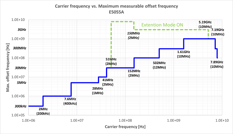
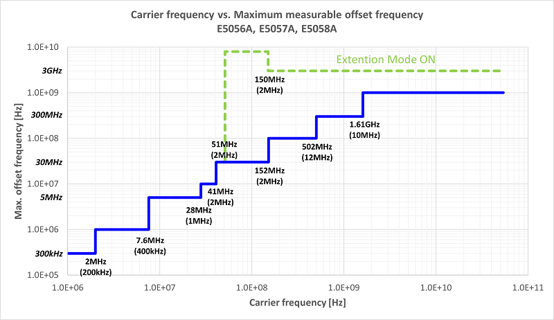
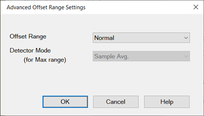
Offset Range ... - Specifies the maximum measurable offset frequency.
Fast XCORR Mode - Make the measurement speed faster by optimizing the acquisition. When user XCORR =1, the behavior is same as the normal XCORR mode. The segment xcorr number is different from the normal XCORR mode. The first and second segment xcorr will be xN when user XCORR is N. This is also applied to segments from 1 MHz to 10 MHz. In the other segment, xcorr will be 0.75*X+0.25*X*N to reduce the measurement time. e.g) segment xcorr is 100 @user xcorr=1 will be 125 @user xcorr=2. The max of segment xcorr is 2e8.
Allan Variance - Tau of AVAR and ADEV:
Start: Larger value of either 100 ns, or reciprocal value of Stop Offset frequency
Stop: Reciprocal value of Start Offset frequency