N1930B PLTS (AFR)
 From the TDR Setup dialog, click the Launch AFR Wizard to start the Keysight N1930B Physical Layer Test System's Automatic Fixture Removal (AFR). AFR's de-embedding algorithm has been directly ported into FlexDCA. In FlexDCA, there is also an additional Quick PLTS AFR which leverages and simplifies the standard AFR.
The power of AFR is that it:
- Characterizes the response of a fixture that has a non-connectorized port. Both single-ended/differential fixtures and probes can be characterized. For example, this photograph shows a fixture that does not have connectors on the DUT side of the fixture.
- Saves an S-parameter Touchstone file (.s2p or .s4p) for importing into a FlexDCA Fixture Component. Fixture Components model the component to be de-embedded.
AFR in FlexDCA cannot be remotely controlled. The are no remote programming commands for AFR.
Typical AFR Use Case
Most of the time, you'll use AFR to characterize test setups that have a single-ended fixture with an RF connector on one end and a non-connectorized end at the DUT as shown in this picture. The "fixture" may not even be a PC board but instead, for example, a probe. Simply connect the TDR head to the fixture's connector and create an "open" or "short" at the non-connectorized end.
Custom Characterization Boards
The following diagrams show a typical combination of DUT and fixture for single-ended and differential measurements. For multi-port single-ended DUT measurements, trace coupling is not removed. For multiport differential test fixtures, trace coupling between the differential traces is removed.
| Single-Ended | Differential (Balanced) |
|---|---|
|
|
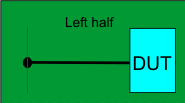
For most situations, you'll want to create custom characterization boards consisting of a 2x Thru, right 1X Thru half, or left 1X Thru half as shown in the following pictures. Both the test fixture and characterization boards should be made of the exact same material, preferably fabricated on the same piece of board as the fixture.
When characterizing your fixture, the AFR wizard will prompt you for the type of characterization board used: 2X Thru or 1X Thru. Use a 2X Thru characterization board if available. If not, use a 1X Thru characterization board, with an open at the desired TDR reference plane as a start. Using an open reference plane is an extremely fast and easy test to see if the fixture open works well or not. If the fixture open radiates too much (like a SMA male connector would), then the next step is to try a 1-port AFR with a short at the fixture output. These are both very easy to test without building special calibration standards. If neither of these two methods work, then the best practice might be to build a 2X Thru standard and use following the 2X Thru AFR method.
Before starting the AFR process, perform a calibration at the test fixture connectors which are identified by the red lines in the diagrams in this topic. The AFR Wizard guides you through these steps:
- Describe your fixturing situation.
- Specify how the Thru fixture characterization will occur.
- Perform characterization.
- Remove the effects of the test fixture, leaving only the displayed results of the DUT.
- Touchstone files are saved and automatically used to characterize the two halves of the test fixture.
Requirements
- Test fixture and either a 2X Thru or left and right 1X Thru halves, all shown below. The fixture itself can be used as a left or right Thru half.
- Left and right 1X Thru half (for 1-port DUTs).
Test Fixtures
| Single-Ended | Differential (Balanced) | |
|---|---|---|
| 2X Thru | ||

|

|
|
| Left half of 2X Thru | ||

|

|
|
| Right half of 2X Thru | ||

|

|
|
To verify a 2X Thru reponse
Ideally, your 2X Thru should be perfectly symmetric, meaning that S11 = S22 and S12 = S21. Use the following steps in FlexDCA to compare the S-parameters:
- Click File > S-Parameter Viewer / Memories.
- In the S-Parameter Memory dialog, select a Memory tab..
- Click Load From File and load the S-parameter file for the 2X Thru.
- Click the New Chart icon to create a Magnitude chart.
- Click Select All to display all of the S-parameters and close the dialog.
- Visually compare the responses to determine the level of symmetry.