Full AFR. Step 1
Describe Fixture
For experienced PLTS users, performing steps 1 through 4 of the full PLTS AFR offers more fixture measurement options than using the Quick AFR characterization.
This topic describes the available selections for the Full AFR's Step 1. Describe Fixture tab. The version number for AFR is shown in the upper-left portion of the dialog and is added to the AFR extracted touchstone file. This information helps to determine which algorithm was used.
To configure AFR settings, click this dialog's settings button (![]() ).
).
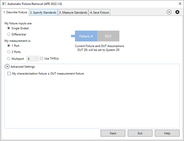
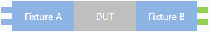
My fixture inputs are and My measurement is
| Measurement | Fixture Inputs | |
|---|---|---|
| Single Ended Fixture and DUT have single-ended inputs and outputs. |
Differential Fixture and DUT have differential inputs and outputs |
|
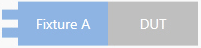
| 1 Port |
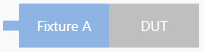
Example: S11 Current fixture and DUT Assumptions: DUT Z0 will be set to System Z0 |
|
| 2 Port |
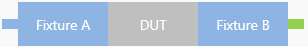
Example: S21 Current fixture and DUT Assumptions: Fixture Match: A ≠ B Fixture Length: A = B DUT Z0 will be set to System Z0 |
Example: SDD11 Current fixture and DUT Assumptions: DUT Z0 will be set to System Z0 |
| 4 Port |
Example: SDD21 Current fixture and DUT Assumptions: Fixture Match: A ≠ B Fixture Length: A = B DUT Z0 will be set to System Z0 |
|
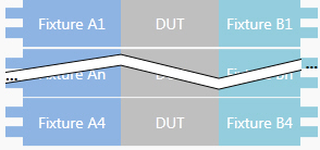
| Multiport |
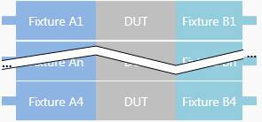
Select up to 32 ports. Current fixture and DUT Assumptions: Fixture Match: A ≠ B Fixture Length: A ≠ B DUT Z0 will be set to System Z0 |
Select up to 32 ports. Current fixture and DUT Assumptions: Fixture Match: A ≠ B Fixture Length: A ≠ B DUT Z0 will be set to System Z0 |
After fixture removal set Calibration Reference Z0 to: (Advanced Settings)
System Z0. Sets impedance to the System Impedance setting.
Measured Fixture Z0. Sets system impedance to the value that is measured during the AFR process. For example, if de-embedding fixtures designed for a device having an input and output impedance of 42.5Ω, the system impedance will be set to 42.5 Ω automatically. The input and output impedance must be the same to use this function. This selection is not allowed if the My fixture is band limited (use Bandpass time domain mode) setting in this tab is selected. Changing the port impedance setting changes the measured S-parameter data.
Ohms. Sets impedance to an arbitrary value. Changing the port impedance setting changes the measured S-parameter data.
Set 'System Z0' to Calibration Reference Z0. When the impedance is measured or set to an arbitrary value, check to also set the System Z0 to the same value. Changing the System Z0 setting does not change measured S-parameter data.
Additional Advanced Settings
I want to correct for Fixture Length A ≠ B. Make this selection when to the electrical length of fixture A does not equal the electrical length of fixture B.
My fixture is band limited (use Bandpass time domain mode). Bandpass mode will be used during the time-domain measurement. If this item is not selected, the lowpass mode is used.
My characterization fixture ≠ DUT measurement fixture. In some cases, the 2x thru is different from the actual DUT measurement fixture but the 2x thru is used to characterize the fixture. In these cases, gating on the DUT measurement fixture is performed that accounts for the fixture input reflection (S11a) and output reflection (S22b) to improve accuracy.