Hardware Diagram
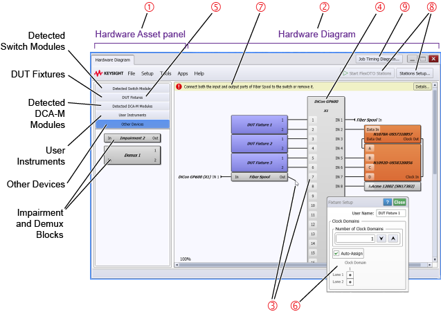
The following picture shows FlexOTO's Hardware Asset pane, Hardware Diagram, and Station control buttons.
- The Hardware Asset pane 1 includes blocks that represent hardware in your test setup.
- The Hardware Diagram 2 represents connections between the optical switch and other hardware. When FlexOTO opens, FlexOTO automatically identifies a supported switch and all supported DCA-M modules. Use the Hardware Diagram to model the equipment setup that you want.
- The actual physical fibers do not need to be connected as you build the Hardware Diagram.
- An Optical Switch and DCA-M modules must by connected and powered on so that the hardware can be detected.
- When your diagram is complete, physically connect the cables on the actual hardware to match the connections shown on your Hardware Diagram.
- If FlexOTO has not automatically placed the optical switch on the Hardware Diagram, from the Detected Switch Module panel 5, drag and drop a detected optical switch to the Hardware Diagram 2. For an optical switch that has multiple internal switch modules, you can cascade the switch modules.
- Observe messages 7 that are displayed in the Configuration Tips area. These messages prompt you to take any required actions to finish the Hardware Diagram.
- The Station control buttons 8 start and stop OTO Stations and determine the number of Stations and their Fixture assignments. Click Start Stations to launch the number of Station processes you have defined. Stations allow you to create test plans with your measurements. If a Configuration Tip is displayed 7, the Start Stations button is disabled until you create a valid Hardware Diagram.
- Drag and drop other hardware asset blocks from the Hardware Assets pane 1 to the Hardware Diagram:
- Fixtures, WDM fixtures, Impairments, and Demultiplexers to the left side of the Hardware Diagram.
- DCA-Ms and Instruments to the right side of the Hardware Diagram. DCA-M instruments form Acquisition-Analysis groups.
- Press the keyboard's SHIFT key while dragging blocks onto the Hardware Diagram so that FlexOTO can automatically make preliminary switch connections. You can easily change them if you want.
- Click the ports 3 on the hardware blocks and the switch block to draw cable connections in you setup.
- When a fixture uses wavelength division multiplexing, the connection line includes a slash next to a digit to indicate lanes are multiplexed as shown in this picture.
- In the DUT Fixtures asset panel, you can specify the Number of Lanes on all DUT Fixtures and WDM DUT Fixtures in the Hardware Diagram. All Fixtures have the same lane counts.
- Double clicking on most diagram blocks opens a Setup dialog 6. All blocks except for DCA-Ms have setup dialogs. Be sure to click on them! The following table lists the available settings on Setup dialogs:
FlexOTO automatically detects a connected optical switch. If a supported switch is not connected, the Hardware Diagram is blank and you must connect a switch.
Avoid damaging the inputs of DCA-M modules. The front panel of many optical switches list the maximum power above which the switch is damaged. Be aware that the switch's maximum power level may far exceed the maximum safe power limits to DCA-M module inputs. Never exceed the maximum power level shown on the DCA-M module's front panel.


Typically, a port on the Hardware Diagram can only be connected to one other port. However, an N1078A's Clock Out port can be connected to the Clock In port on multiple N1092D modules. Click first on the N1092D's Clock In port and afterward click on the N1078A's Clock Out ports. Clicking first on the N1078A's Clock In port will not allow you to make multiple connections.
| Switch Block | Settings | |||
|---|---|---|---|---|
| User Name | Clock Domains | Nominal Attenuation |
Instrument Connection Setup Dialog |
|
| DUT & WDM DUT Fixture | ● | ● | ||
| Demultiplexer | ● | ● | ||
| Impairment | ● | ● | ||
| Instrument | ● | ● | ||
- After running your Stations, click Job Timing Diagram 9 that you want and assign one or more fixtures to each Station. Stations are useful for asynchronous testing as explained here. If multiple Stations are used, each Station must be assigned at least one fixture. Click on the fixture table to assign fixtures to Stations.