N1055A Module Specifications
N1055A module specifications and characteristics apply when a module is installed in the instrument mainframe. The following notes refer to the module specifications listed in this chapter.
- N1000A Regulatory Information and Instrument Markings
- 86100D Regulatory Information and Instrument Markings
This module requires an 86100D DCA-X mainframe a minimum FlexDCA firmware version of A.04.00.
All specifications describe warranted performance over the temperature range +10° C to + 40° C (unless otherwise noted). The specifications are applicable after the temperature is stabilized, which occurs after 1 hour of continuous operation and while module calibration is valid. Many performance parameters are enhanced through frequent, simple user calibrations.
Specifications describe warranted performance. Characteristics provide useful, nonwarranted information about the functions and performance of the instrument. Characteristics are printed in green italics.
Factory Calibration Cycle. For optimum performance, the N1055A should have a complete verification of specifications once every 12 months.
Nominal Value indicates the expected, but not warranted, value of the parameter.
N1055A General Specifications
| Item | Module Options1 N1055A-32F N1055A-32M |
Module Options1 N1055A-34F N1055A-34M |
Module Options1 N1055A-52F N1055A-52M |
Module Options1 N1055A-54F N1055A-54M |
|---|---|---|---|---|
| Number of Channels | 2 2 | 4 | 2 2 | 4 |
| Remote Head Cable Length | The nominal length of the remote head cables is 1270 mm as measured from the module's front panel to the remote head's casing. | |||
| Electrical Input 3 | 2.92 mm (female or male) | 1.85 mm (female or male) | ||
| Electrical Channel Bandwidth | 35 GHz 4, 5 | 35 GHz or 50 GHz 5 | ||
| Receiver Transition Time
(10% to 90% calculated from TR = 0.35/BW) |
10 ps, characteristic | 10 ps (35 GHz BW setting), characteristic 7 ps (50 GHz BW setting), characteristic |
||
| Channel-to-Channel Skew Range | ± 150 ps | |||
| Vertical Resolution | 16 bit A/D converter | |||
| RMS Noise | 600 μV, characteristic
730 μV, maximum |
600 μV (35 GHz BW setting), characteristic
750 μV (50 GHz BW setting), characteristic 950 μV (50 GHz BW setting), maximum |
||
| Scale Factor (Per Division) | Description | |||
| Minimum | 1 mV / division | |||
| Maximum | 100 mV / division | |||
| DC Accuracy (VAVG Measurement) | ± 800 uV, characteristic
Specified at calibration temperature ± 0.5 °C. (Perform a new module calibration if hardware skew has been applied.) |
|||
| ± 2 mV ± 4% of (reading–channel offset) Specified at calibration temperature ± 10 °C |
||||
| DC Offset Range
(referenced from center of screen) |
± 500 mV | |||
| Input Dynamic Range
(relative to channel offset) |
± 400 mV | |||
| Maximum Input Signal | +2 V / –1 V | |||
| Nominal Impedance | 50 ohm | |||
| Maximum Sample Rate, module timebase 6 | Description | |||
| Option-FS1 | 250 kSa/s, characteristic | |||
| Standard | 80 kSa/s, characteristic | |||
| TDR Step Repetition Rate 6 | Description | |||
| Mainframe Timebase | 1 kHz to 250 kHz, characteristic | |||
| Module timebase (standard) | 1 kHz to 80 kHz, characteristic | |||
| Module timebase (Option FS1) | 1 kHz to 250 kHz, characteristic | |||
Connectors: F = female, M = male.
Upgradable from 2 channel to 4 channel after purchase (return to Keysight).
Connector style is the same on all channels and is selected at time of order.
Upgradable from 35 GHz to 50 GHz after purchase (return to Keysight).
Tuned to be –3 dB (± measurement uncertainty) at stated bandwidth(s) using NIST traceable swept-sine test system.
FlexDCA software auto-selects the mainframe or module timebase dependent on the DUT setup. In cases where the mainframe timebase is used, the maximum sample rate will be:
86100D Mainframe: 40 kSa/s for standard modules and modules with option-FS1, (characteristic).
N1000A Mainframe: 80 kSa/s for standard modules and 250 kSa/s for modules with option-FS1, (characteristic).
N1055A TDR System Specifications
| Item | Module Options1 N1055A-32F N1055A-32M N1055A-34F N1055A-34M |
Module Options1 N1055A-52F N1055A-52M N1055A-54F N1055A-54M |
|---|---|---|
| Incident TDR Step Transition Time (10 % to 90 %) 2, 3 | Description | |
| Without TDR Calibration | < 18 ps | < 7 ps |
| With TDR Calibration | Adjustable from 15 ps, characteristic | Adjustable from 6 ps, characteristic |
| Reflected TDR Step Transition Time (10% to 90%) 3 | Description | |
| Without TDR Calibration | < 20 ps | < 11 ps |
| With TDR Calibration | < 18 ps | 9.5 ps, characteristic |
| TDR Step Amplitude (Combined Oscilloscope and TDR Performance) | 100 mV Setting: 0 mV to ± 100 mV 200 mV Setting: 0 mV to ± 200 mV |
100 mV Setting: 0 mV to ± 100 mV 200 mV Setting: 0 mV to ± 200 mV |
Connectors: F = female, M = male.
Incident TDR edge speed is defined as the transition time at the output of the remote head. It is calculated by de-convolving the receiver transition time from the measured transition time when the remote head is terminated with a short.
Measured on a negative TDR step, terminated in a short.
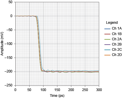
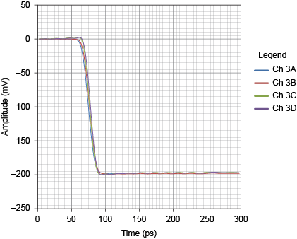
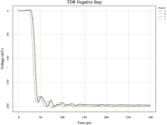
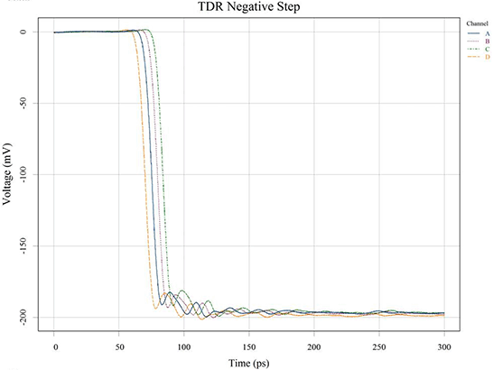
Step Flatness (Graphs of Combined Oscilloscope and TDR Performance)
|
|
In the following two graphs, the blue trace shows Channel A, the red trace shows Channel B, The green trace shows Channel C, and the yellow trace shows Channel D.
|
|
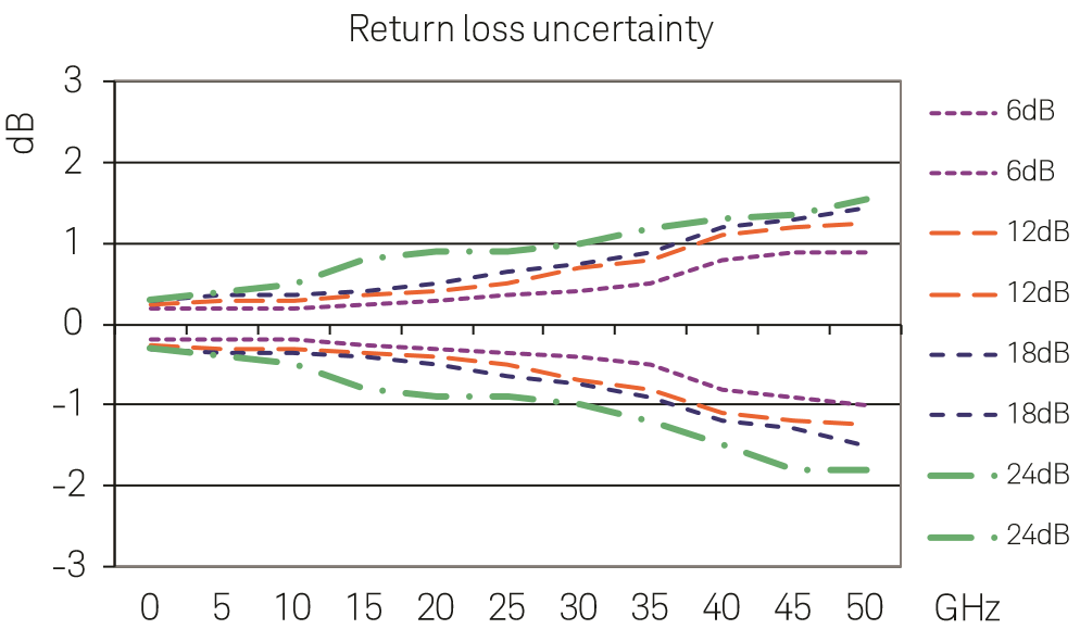
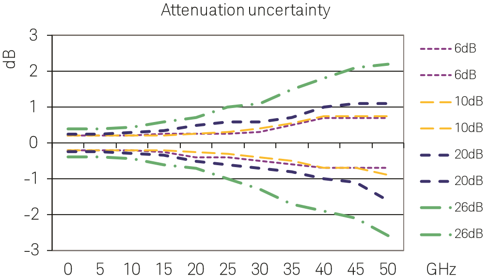
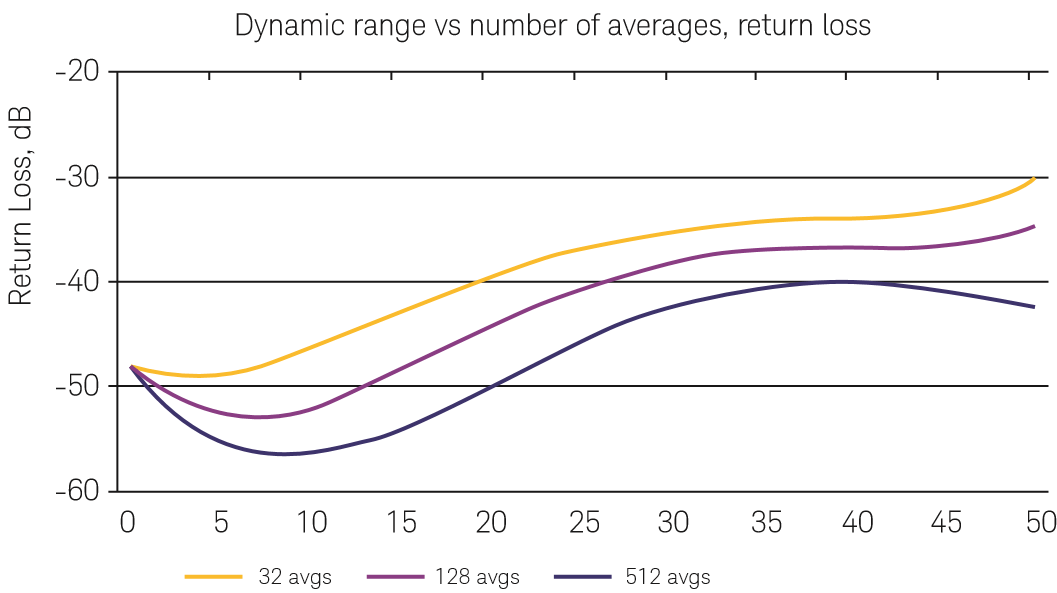
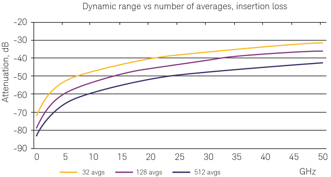
N1055A Performance Characteristics
Apply when N1055A used with N1010300A Signal Integrity Package for FlexDCA Sampling Oscilloscope Software. Test conditions:
- Mainframe and module have been turned on for at least one hour and have been calibrated
- TDR calibration has been performed using appropriate electronic or mechanical calibration units
- Derived from measurements made on 1.85 mm verification devices that were calibrated by Keysight metrology lab
- Averages of 512 except as noted in dynamic range
|
|
|
|