Jitter Spectrum Analysis Setup

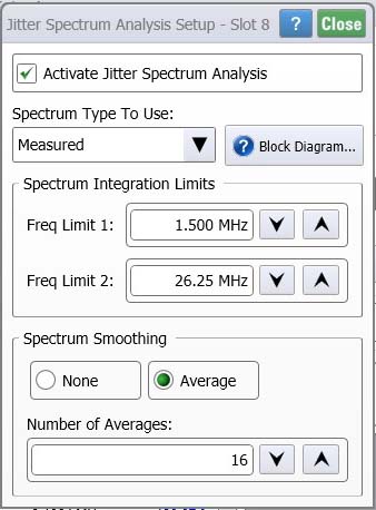
Clicking the JSA/CRE toolbar's JSA Setup button opens the Jitter Spectrum Analysis Setup dialog.
In the dialog, enter the appropriate settings and then click Activate Jitter Spectrum Analysis to turn on JSA and display the Jitter Spectrum Analysis Results panel. This is equivalent to clicking the JSA/CRE toolbar's Activate JSA button.
The JSA toolbar is available in Oscilloscope, Eye/Mask, and Jitter modes when a required module is installed and license is installed as indicated in the following two notes.
JSA requires an N1060A, N1076A, N1076B, N1077A, N1077B, or N1078A clock-recovery module that has Option JSA.
JSA requires license packages N1010100A RND and N1010300A SI to enable the JSA option for the N1076B, N1077A, N1077B, N1078A and N1092A/B CDR clock-recovery module which requires FlexDCA firmware version A.07.40 or later.
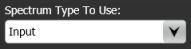
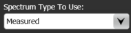
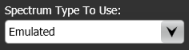
Spectrum Type To Use
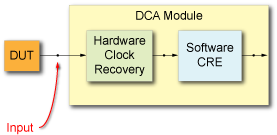
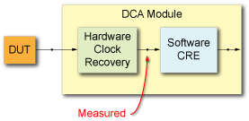
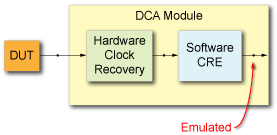
The Spectrum Type To Use field configures JSA's view of low-frequency jitter. Select one of three references for jitter measurements: Input, Measured, or Emulated. The following table provides a description of these selections. Use the Jitter Spectrum Analysis Graph to view the observed jitter spectrum based on the selected signal. Click Block Diagram to view the location of the spectrum for each spectrum. The block diagram is also shown in the following table.
| Selection | Description |
|---|---|
|
Available in Oscilloscope or Eye/Mask mode, the Input spectrum type allows you to view all of the low-frequency jitter on your signal. This is the recovered clock with the effects of the clock recovery PLL de-embedded. This selection is not available in Jitter Mode.

This button is available whenever the hardware clock-recovery loop bandwidth is not set to a minimum value and is thus not configured for optimum input spectrum fidelity. When clicked, the hardware CDR loop bandwidth is set to the lowest possible value while still maintaining lock and the loop characteristics are automatically selected. These two settings can be manually set in the Setup dialog's Clock Recovery tab. You may need to manually adjust these settings if the lock is unstable. The goal is to set the loop bandwidth (Target LBW) to the narrowest loop bandwidth possible while still maintaining lock. Do not set the Target LBW for the desired loop bandwidth of the receiver. |
|
Available in Oscilloscope, Eye/Mask, and Jitter modes. This is the default selection. The Measured spectrum type complements Jitter Mode by showing the distribution of low-frequency jitter. It enables you to discover the root cause of jitter in your device. (Jitter Mode integrates jitter over a larger spectrum resulting in larger RJ measurements.) In the Setup dialog's Clock Recovery tab, configure the dialog's Target LBW field with the specified bandwidth for the applicable standard. In the dialog's Advanced Type Two Loop Transition Frequency (Peaking) field, enter the peaking setting recommended by the applicable standard.
|
|
Available in Oscilloscope, Eye/Mask, and Jitter modes. Emulated allows you to view low-frequency jitter response to a wide variety of user-specified clock recovery (PLL) configurations. While using hardware clock recovery, clock recovery emulation (CRE) is used to measure the incoming signal relative to an ideal software clock-recovery response.
The Setup field is only shown in the dialog when the Emulated spectrum type is selected. Use this feature to view low-frequency jitter response to a wide variety of user-specified clock recovery (PLL) configurations. It uses the software emulated recovered clock as the reference. Click Setup to configure the Clock Recovery Emulation (CRE). 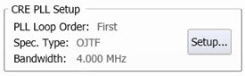
|
Spectrum Integration Limits
Use the Spectrum Integration Limits field to define the lower (Freq Limit 1) and upper (Freq Limit 2) frequency integration FFT limits for the jitter spectrum. On the displayed Jitter Spectrum graph, the  and
and  symbols mark the location of the integration limits.
Spectrum Smoothing
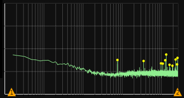
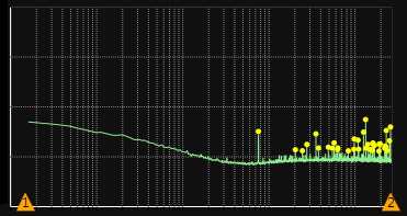
Use the Spectrum Smoothing field to apply averaging to the FFT magnitude and specify the Number of Averages. The default number of averages is 16. Increasing the number of averages allows you to view peaks that are hidden in the noise.
Number of Averages: 2
Number of Averages: 16
Signal Type
Use the Signal Type field to specify the calibration factors that are applied to the phase detector gain correction. The calibration factors can be for either NRZ or PAM signal types as well as single ended or differential. By default, this selection is set to Automatic where FlexDCA automatically determines the signal type.