Configure CRE PLL

Use the Configure CRE PLL dialog to configure the emulated clock-recovery PLL. Adjustable parameters include loop order, 3 dB bandwidth, peaking, and damping factor. The ability to configure the Clock Recovery Emulation PLL is available in Oscilloscope, Eye/Mask, and Jitter modes when the Emulated spectrum types is selected.
To open this dialog
- In the JSA Setup dialog, select the Emulated spectrum type, and click Setup.
- In Jitter Mode, click the CRE PLL Setup toolbar button
- In the Jitter Mode Measurements Setup dialog's Advanced tab, click Setup CRE PLL….
Select the PLL Loop Order
At the top of the dialog, select the PLL Loop Order. Because the dialog changes depending on the loop order selected, each of the three loop order selections have their own description within this topic:
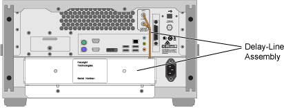
Delay Matching
This informational message warns you about additional requirements when using Clock Recovery Emulation (CRE) with the following hardware:
- External Clock Recovery is used (for example, N107x-series DCA-M) and
- N1000A-PTB Internal Precision Time Base is used.
In this situation, you must ensure that the clock-to-data path delays are matched. The recommended N1027A-76A electrical clock recovery phase matching kit provides a delay-line assembly that adds the required amount of delay. As shown in the following picture, the delay-line assembly attaches to the N1000A's rear panel to replace a rear-panel jumper cable. For instructions on installing the delay line with drawings of example test setups, download the N107x-series user's guide from keysight.com. You do not need to worry about adding delay, if you are using an N1060A precision waveform analyzer module.
Hardware CDR Loop Bandwidth
 After configuring the CRE PLL, click this button (located at the bottom of the dialog) to obtain the optimum CRE spectrum fidelity. This function automatically matches, as closely as possible, the hardware CDR parameters to the CRE PLL settings. You can manually configure these settings by opening the N1060A or N107x-series DCA-M Setup dialog's Clock Recovery tab and configuring the Loop Bandwidth and Loop Characteristics fields to the desired specification.
First Order PLL Loop
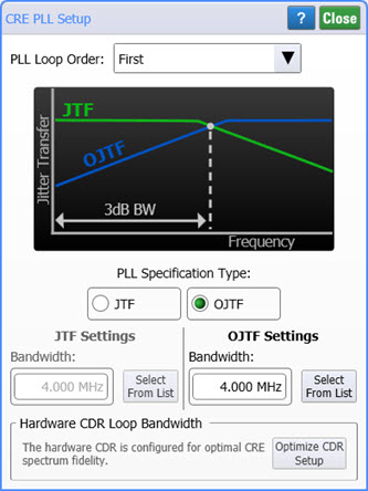
For first-order loops, select to define either the Jitter Transfer Function (JTF) or Observed Jitter Transfer Function (OJTF). Enter the bandwidth. The following table shows the bandwidth settings defined for some standards. In the dialog's Jitter Transfer diagram, notice that the JTF and OJFT functions share the same 3 dB bandwidth.
| Standard | JTF Bandwidth | OJTF Bandwidth |
|---|---|---|
| SAS 1.5 GBd | 900.0 kHz | 890.9 kHz |
| SAS 3.0 GBd | 1.800 MHz | 1.782 MHz |
| SAS 6.0 GBd | 3.600 MHz | 3.564 MHz |
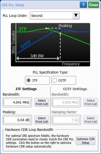
Second Order PLL Loop
For second-order loops, select to define either the Jitter Transfer Function (JTF) or Observed Jitter Transfer Function (OJTF). When defining the JTF function, enter the Bandwidth and Peaking. When defining the OJTF function, enter the Bandwidth and the Damping Factor.
In the dialog's Jitter Transfer diagram,

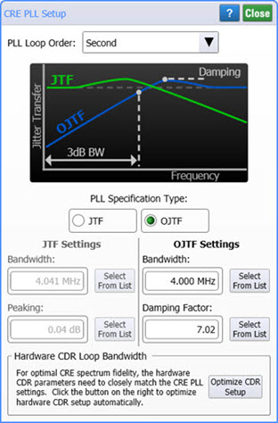
The following table shows the bandwidth settings defined for some standards.
| Standard | JTF Settings | OJTF Settings | ||
|---|---|---|---|---|
| Bandwidth | Peaking | Bandwidth | Damping Factor | |
| SAS 1.5 GBd | 900.0 kHz | 0.04 dB | 890.9 kHz | 50.0 |
| SATA 3.0 GBd | 1.791 MHz | 1.57 dB | 1.000 MHz | 0.860 |
| SAS 3.0 GBd | 1.800 MHz | 0.04 dB | 1.782 MHz | 50.0 |
| SAS-SSC 1.5 GBd | 2.328 MHz | 1.57 dB | 1.300 MHz | 0.860 |
| SAS-SSC 3.0 GBd | 3.291 MHz | 1.57 dB | 1.838 MHz | 0.860 |
| SAS 6.0 GBd | 3.600 MHz | 0.04 dB | 3.564 MHz | 50.0 |
| SATA 1.5 GBd | 4.097 MHz | 1.86 dB | 2.100 MHz | 0.767 |
| SAS-SSC 6.0 GBd | 4.655 MHz | 1.57 dB | 2.600 MHz | 0.860 |
| QPI | 5.692 MHz | 1.75 dB | 3.000 MHz | 0.800 |
| SATA 6.0 GBd | 8.194 MHz | 1.86 dB | 4.200 MHz | 0.767 |
| USB 3.0 | 10.03 MHz | 2.08 dB | 4.900 MHz | 0.707 |
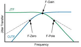
Third Order PLL Loop
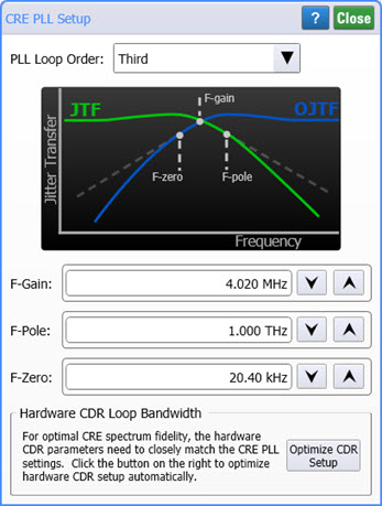 For a third-order loop, define the low-pass filter by entering the frequency of the gain, pole, and zero. In the F-Zero field, enter the frequency at which the OJTF starts to roll-off at 40 dB/decade. In the F-Pole field, enter the frequency at which the JTF starts to roll-off at 40 dB/decade. In the F-Gain field, enter the frequency that sets the approximate loop bandwidth of the PLL.
with Zero, Pole, and Gain Frequencies