Jitter Mode Setup (Advanced tab)
Advanced with RJ/RN Separation Method
Use the Advanced tab of the Jitter Mode Measurements Setup dialog, to configure advanced jitter mode settings. In this picture, click on the Separation Method, Stabilization and RJ/RN Compensation tabs to learn more.
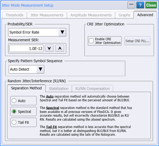
Probability/SER
Use to specify PAM4 jitter analysis to be based on probability or Symbol Error Ratio (SER). TJ, TI, eye width, and eye height measurements in the latest standards are made at probabilities instead of SER.
CRE Jitter Optimization

If JSA is available, the CRE Jitter Optimization field will be displayed. Select Enable CRE Jitter Optimization to apply clock-recovery emulation to Jitter Mode's RJ measurement. This feature is only available if JSA is turned on in Jitter mode and the JSA spectrum is set for Embedded. You can also apply jitter optimization by clicking the CRE Jitter Optimize button that is located on the JSA/CRE toolbar. Click the Setup CRE PLL button to configure the clock-recovery PLL emulation.
CRE Jitter Optimization is only available if an N1060A or 86108A/B Option JSA module is installed in the DCA-X. Installing this module makes available Jitter Spectrum Analysis on FlexDCA.
Specify Pattern Symbol Sequence
Use this setting to specify the input waveform's pattern symbol sequence (NRZ or PAM4). As shown in the following picture, you can select to have the pattern automatically detected (default), select from a standard Known Pattern, or import a BERT Pattern File (*.ptrn). Available known patterns are listed in the following table. If you select to import a PAM4 Pattern File, you should indicate if the pattern uses Gray Coding. Gray coding, or reflected binary code, is a coding pattern where successive symbols differ by one binary bit. For example in the case of PAM4, binary bit sequences 00, 01,10, and 11 represent levels 0, 1, 2, and 3.
Pattern Length Selections
Availability of individual patterns depends on installed modules and other conditions.
- 20 - 2˄7-1 PRBS
- 40 - PCIe Compliance
- 62 - PAM4 Clock
- 120 - FC RPAT
- 160 - PAM4 Linearity
- 384 - 802.3ae TWDP segment
- 640 - PCIe Idle
- 1280 - FDDI Jitter
- 2280 - CRPAT
- 2640 - CJPAT
- 3360 - CRPAT (2)
- 3760 - CJPAT (2)
- 3780 - XAUI CRPAT
- 3820 - XAUE CJPAT
- 5280 - GbE Test Frame
- 7641 - XAUI CJPAT
- 9000 - JTPAT
- 18944 - CEI Stress
- 20480 - SPAT
- 20840 - CSPAT
- 21760 - CJTPAT
- 30240 - XAUI CRPAT
- 32762 - CEI SSPR
- 33792 - 10GbE
- 65535 - SSPRQ
- 90000 - FDDI Wander
- 92160 - SATA
- 311040 - SONET CID
- 127 - 2˄7-1 PRBS
- 128 - 2˄7 PRBS
- 511 - 2˄9-1 PRBS
- 512 - 2˄9 PRBS
- 1023 - 2˄10-1 PRBS
- 1024 - 2˄10 PRBS
- 2047 - 2˄11-1 PRBS
- 2048 - 2˄11 PRBS
- 8191 - 2˄13-1 PRBS
- 8192 - 2˄13 PRBS
- 32767 - 2˄15-1 PRBS
- 32768 - 2˄15 PRBS
- 65535 - 2˄16-1 PRBS
- 65536 - 2˄16 PRBS
- 1048575 - 2˄20-1 PRBS
- 1048576 - 2˄20 PRBS
- 8388607 - 2˄23-1 PRBS
- 8388608 - 2˄23 PRBS
Separation Method Selection
This setting determines the method used to decompose RJ and RN. There are three choices: Auto, Spectral, and Tail Fit. The recommended setting is Auto, which automatically selects the spectral or tail fit method to ensure the most accurate RJ and RN measurements. A significant presence of Bounded Uncorrelated Interference (BUI) or Bounded Uncorrelated Jitter (BUJ) on a signal, may adversely affect the RJ and RN measurements, and the Tail Fit method is designed to correct this. However, manually selecting the Tail Fit selection is not recommended.
The following table shows how the Separation Method affects the measurement algorithm as well as the measurements reported in the Jitter and Amplitude results panels. When Auto is selected, both the Spectral and the Tail Fit methods are performed for each edge type: rising and falling. The resulting RJ and RN values are compared between the two methods, with the value reported for an edge type based on the criteria shown in the following table. Depending on the data, the value for different edge types can be calculated using different methods. Regardless of the methods used in Auto, the measurement panel always reports results for both BUJ and BUI parameters.
The Spectral separation method uses the aliased spectrum, obtained from the RJ/PJ or RN/PI histograms, to measure RJ / RN. This is the Legacy Jitter Mode algorithm and provides the highest accuracy for signals that have small amounts of Bounded Uncorrelated Jitter/Noise (such as cross talk), which can degrade RJ measurements. Uncertainties are determined from the variance of the variance of the RJ/PJ histogram.
The Tail Fit separation method uses the RJ/PJ and RN/PI histogram data also but instead of using the aliased spectrum to compute RJ and RN this method performs a straight-line fit to the Q-scale tails of the Cumulative Distribution Function (CDF). This method is optimized for data signals with medium to high levels of Bounded Uncorrelated Jitter/Noise (such as cross talk). Uncertainties for the Tail Fit method are determined by the variance of the slope of the straight line fit of the Q-scale tails of the CDF.
| Separation Selection | Separation Method Used |
Measurement Reported in Tables | |
|---|---|---|---|
| Jitter Table | Amplitude Table | ||
| Auto Selected | |||
| Definitions: TF = Tail Fit method. SP = Spectral method. | |||
| If RJ TF + tail-fit uncertainty ≥ RJ SP – spectral uncertainty | Spectral | BUJ (rms), BUJ (δ - δ) |
not applicable |
| If RJ TF + tail-fit uncertainty < RJ SP − spectral uncertainty | Tail Fit | ||
| If RN TF + tail-fit uncertainty ≥ RN SP – spectral uncertainty | Spectral | not applicable | BUI (rms), BUI (δ - δ) |
| If RN TF + tail-fit uncertainty < RN SP − spectral uncertainty | Tail Fit | ||
| Spectral Selected | Spectral | PJ (rms), PJ (δ - δ) |
PI (rms), PI (δ - δ) |
| Tail Fit Selected | Tail Fit | BUJ (rms), BUJ (δ - δ) |
BUI (rms), BUI (δ - δ) |