Jitter Mode Setup (Thresholds tab)
Thresholds
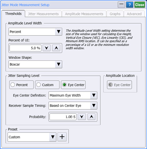
Use the Thresholds tab of the Jitter Mode Measurements Setup dialog to configure Amplitude Level Width (PAM4 waveforms) and Jitter Sampling Level (NRZ and PAM4 waveforms) settings. Thresholds are used to determine the various waveform levels. The fields that are shown in this tab change depending on whether the signal used NRZ or PAM4 formatting. When the instrument is in Jitter Mode, you can also click the Setup & Info on the Results or Frequency panels.
Amplitude Level Width (PAM4 Signals). The Amplitude Level Width fields are displayed in the dialog only when the input signal is PAM4. These settings affect the size of the window for calculating Eye Height, Vertical Eye Closure (VEC), Eye Linearity (CED), and Minimum RMS location. The Amplitude Level Width can be defined as a Percent (default setting) or Minimum value. When Percent is selected, enter the Percent of UI (default value is 5.0%) and select the Window Shape (Boxcar or Gaussian). If you select Gaussian, enter the Standard Deviation as a Percent of the UI. The default value is 2.0%.
The Thresholds tab does not apply to 12-Edge Output Jitter measurements.
The following picture shows the Thresholds tab.
Jitter Sampling Level (NRZ and PAM4)
The Jitter Sampling Level fields are shown for both NRZ and PAM4 signals. By default, the sampling level is set to Eye Center but you can change it to Percent or a Custom level.
When Eye Center is selected, you can set the:
- Eye Center Definition to maximum Eye Width or Eye Height.
- Receiver Sample Timing based on Center Eye or Independent Per Eye.
- Probability at which to perform the measurement. The default value is 1.0E-6.
- Amplitude Location is set to Eye Center. As a default, the data is sampled at a logic crossing time (the transition point between low and high logic values) that is set at default to 50% of the average value for logic highs and lows.
When Custom is selected:
- Set the Eye (NRZ) or each individual eye (PAM) to a set amplitude (Watts or Volts based on the optical or electrical input channel used).
- Amplitude Location for each level to a percentage (default is 50.0% for each level) or Minimum RMS.
When Percent is selected:
- Set the Eye (NRZ) or each individual eye (PAM) as a percent of the eye amplitude.
- Amplitude Location for each level to a percentage (default is 50.0% for each level) or Minimum RMS.
 The average value for each logic level is measured at the symbol-center time. The sampled amplitude values are converted to time values as part of the Jitter Measurement Algorithm. By default in Jitter Mode, the underlying eye diagram, from which all jitter measurements are derived, is displayed in the Waveform panel. Select the Waveform tab to view the Waveform panel.
Figure. Sample Level Set to the Default 50% Level
Figure. Sample Level Changed to a 30% Level
The jitter sampling level (volts or Watts) can be queried or listed in the Jitter results panel by using the :MEASure:JITTer:LEVel remote programming command.
Jitter Thresholds Presets
- CEI 56G VSR PAM4
- IEEE 802.3bs PAM4
- IEEE 802.3ck PAM4