Jitter Mode Setup (Jitter Measurements tab)
Jitter Measurements
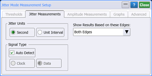
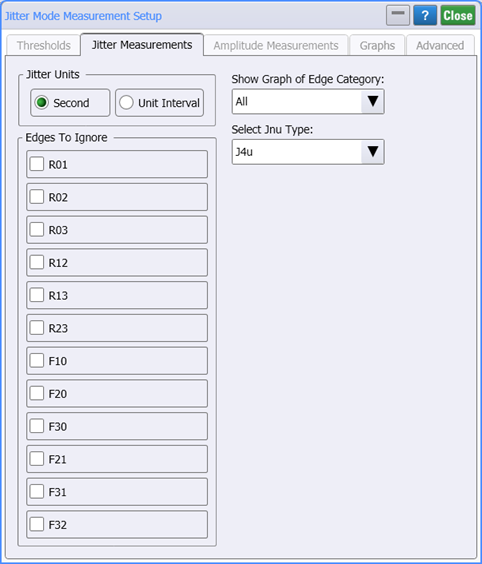
Use the Jitter Measurements tab of the Jitter Mode Measurements Setup dialog to configure jitter measurements. The following pictures show how this tab looks depending on the type of waveform (NRZ or PAM4) and whether the 12-Edge Output Jitter measurements are turned on.

Jitter Units
Select the measurement units for values that are reported on the Results panel and shown on the x-axis of displayed graphs. Choices are Seconds (default value) or Unit Interval (UI), which is the symbol period of the data.
Show Results Based on (NRZ)
For NRZ waveforms, select the type of signal edges to include (and thereby exclude) from the jitter measurement algorithm: Rising, Falling, or Both Edges. These are the symbol edges from which data is acquired for calculating jitter results. The default setting for data signals is Both Edges. The default setting for clock signals is Rising Edges. This setting is also used for the Aliased Spectrum graph. However, because the Aliased Spectrum graph can only be set to use Rising or Falling edges, if Both Edges is selected, this graph defaults to using Rising edges.
Show Graphs Based on (PAM4)
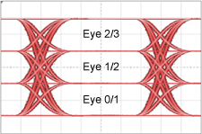
For PAM4 waveforms with 12-Edge Output Jitter turned off, select the waveform eye on which to base the displayed histogram graphs. This includes Eye 0/1, 1/2, or 2/3 as shown in this picture. This setting is also used for the Aliased Spectrum graph.
For PAM4 waveforms with 12-Edge Output Jitter measurement turned on, the Output Jitter Histogram graph are based on a selected edge category which can be:
- One the 12 falling or rising PAM4 edges,
- A composite of Rising 03 edges (R03) and Falling 30 edges (F30), or
- A composite of all edges.
Use the Select Jnu Type field to select the probability at which the measurement is made.
| Selection | Probability |
|---|---|
| J9u | 10–9 |
| J8u | 10–8 |
| J7u | 10–7 |
| J6u | 10–6 |
| J5u | 10–5 |
| J4u | 10–4 |
| J3u | 10–2 |
| J2u | 10–1 |
| J1u | 10–1 |
Signal Type
This field is shown for NRZ signals and is hidden for PAM4 signals. Specify the input signal type: data or clock. As a default, Auto Detect is selected, and FlexDCA automatically detects the signal type. The Signal Type setting can also be accessed on the Pattern Lock Setup tab of the Trigger dialog. If a poorly-defined signal can not be automatically detected, clear the Auto Detect feature. The jitter algorithms used are identical regardless of this setting: Clock or Data. However, the following differences can be seen:
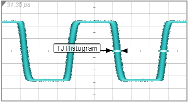
If Clock is selected, a single-valued waveform is displayed, and if Data is selected, the 1010 data pattern is wrapped.
| Clock is selected | Data is selected |
|---|---|
|
|
In the Jitter results panel, the Rate: units and the Pat. Length: values are different.
| Clock is selected (Rate in GHz) | Data is selected (Rate in GBd) |
|---|---|

|

|