Jitter Mode Setup (Advanced tab)
Advanced with RJ/RN Compensation
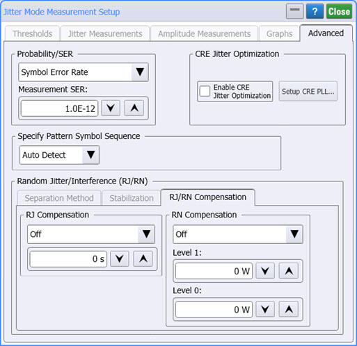
Use the Advanced tab of the Jitter Mode Measurements Setup dialog, to configure advanced jitter mode settings. In this picture, click on the Separation Method, Stabilization and RJ/RN Compensation tabs to learn more.
Probability/SER
Use to specify PAM4 jitter analysis to be based on probability or Symbol Error Ratio (SER). TJ, TI, eye width, and eye height measurements in the latest standards are made at probabilities instead of SER.
CRE Jitter Optimization

If JSA is available, the CRE Jitter Optimization field will be displayed. Select Enable CRE Jitter Optimization to apply clock-recovery emulation to Jitter Mode's RJ measurement. This feature is only available if JSA is turned on in Jitter mode and the JSA spectrum is set for Embedded. You can also apply jitter optimization by clicking the CRE Jitter Optimize button that is located on the JSA/CRE toolbar. Click the Setup CRE PLL button to configure the clock-recovery PLL emulation.
CRE Jitter Optimization is only available if an N1060A or 86108A/B Option JSA module is installed in the N1000A. Installing this module makes available Jitter Spectrum Analysis on FlexDCA.
Specify Pattern Symbol Sequence
Use this setting to specify the input waveform's pattern symbol sequence (NRZ or PAM4). As shown in the following picture, you can select to have the pattern automatically detected (default), select from a standard Known Pattern, or import a BERT Pattern File (*.ptrn). Available known patterns are listed in the following table. If you select to import a PAM4 Pattern File, you should indicate if the pattern uses Gray Coding. Gray coding, or reflected binary code, is a coding pattern where successive symbols differ by one binary bit. For example in the case of PAM4, binary bit sequences 00, 01,10, and 11 represent levels 0, 1, 2, and 3.
Pattern Length Selections
Availability of individual patterns depends on installed modules and other conditions.
- 20 - 2˄7-1 PRBS
- 40 - PCIe Compliance
- 62 - PAM4 Clock
- 120 - FC RPAT
- 160 - PAM4 Linearity
- 384 - 802.3ae TWDP segment
- 640 - PCIe Idle
- 1280 - FDDI Jitter
- 2280 - CRPAT
- 2640 - CJPAT
- 3360 - CRPAT (2)
- 3760 - CJPAT (2)
- 3780 - XAUI CRPAT
- 3820 - XAUE CJPAT
- 5280 - GbE Test Frame
- 7641 - XAUI CJPAT
- 9000 - JTPAT
- 18944 - CEI Stress
- 20480 - SPAT
- 20840 - CSPAT
- 21760 - CJTPAT
- 30240 - XAUI CRPAT
- 32762 - CEI SSPR
- 33792 - 10GbE
- 65535 - SSPRQ
- 90000 - FDDI Wander
- 92160 - SATA
- 311040 - SONET CID
- 127 - 2˄7-1 PRBS
- 128 - 2˄7 PRBS
- 511 - 2˄9-1 PRBS
- 512 - 2˄9 PRBS
- 1023 - 2˄10-1 PRBS
- 1024 - 2˄10 PRBS
- 2047 - 2˄11-1 PRBS
- 2048 - 2˄11 PRBS
- 8191 - 2˄13-1 PRBS
- 8192 - 2˄13 PRBS
- 32767 - 2˄15-1 PRBS
- 32768 - 2˄15 PRBS
- 65535 - 2˄16-1 PRBS
- 65536 - 2˄16 PRBS
- 1048575 - 2˄20-1 PRBS
- 1048576 - 2˄20 PRBS
- 8388607 - 2˄23-1 PRBS
- 8388608 - 2˄23 PRBS
RJ/RN Compensation Tab
The section presents the RJ/RN settings. For additional information, refer to:
RJ Compensation
Use RJ Compensation, to specify a compensation value of RJ that you need applied to the measured result. In the drop-down list select either:
- OFF
- Remove Custom Jitter Value
In the measurement pane, an asterisk is shown next to the RJ (rms) measurement results warning you that the measurement result has been modified. Above the panel the annotation RJ Compensation: lists the entered value.
Use this setting to remove intrinsic oscilloscope jitter from the measurement results. Every jitter measurement, whether performed on a scope, TIA, or BERT, includes a component of jitter that has been generated by the measurement instrument itself. This is often referred to as intrinsic jitter. The RJ result is an RSS sum of RJ from the instrument and Device Under Test (DUT):
RJ2meas = RJ2DUT + RJ2meas system
To determine the intrinsic RJ from your measurement system, measure the jitter of a source that is known to have extremely low phase noise, such as an Keysight E8267D PSG Analog Signal Generator. Alternatively, if you are using a BERT or pattern generator to drive the DUT, connect the BERT or pattern generator directly to the N1000A and measure jitter using a PRBS7 or 1010 pattern. The measured RJ is the intrinsic RJ of your measurement system. Enter this value into the RJ Compensation field and this random jitter contribution will be RSS'd out of the results.
RN Compensation
Use RN Compensation, to specify a compensation value of RN that you need applied to the measured result. Use this setting to remove intrinsic oscilloscope noise from the measurement results. First, estimate the Random Noise that is contributed by the DCA-X by disconnecting all cables and signals from the oscilloscope's input and then measuring Vrms (AC) in Oscilloscope mode. Enter this value into the RN Compensation field, and its contribution to the RN measurement will be removed.
In the drop-down list select either:
- Off
- Remove Scope Noise. For RIN measurements, select this setting.
- Remove Custom Noise Values
In the measurement panel an asterisk is shown next to the *RN (rms) measurement results warning you that the measurement result has been modified. Above the panel the annotation RN Compensation: lists the entered value. Enter RN level values in volts (electrical) or watts (optical), depending on the type of signal that you are measuring.
Click the tabs in the picture at the top of this topic to view information about the other Random Jitter/Interference (RJ/RN) features.