N1093A/B DCA-M Optical Oscilloscopes
The N1093A/B DCA-M optical sampling oscilloscopes are controlled via USB from a PC. The two available models vary in the number of front-panel channel inputs as shown in the following table. The N1093A/B option PLK oscilloscopes can be used with pattern lock. For installation, safety, and regulatory information, refer to the N109X-Series User's Guide which can be downloaded from keysight.com.
An N1093A/B requires FlexDCA firmware version A.08.30 or later.
Maximum Clock In non-destruct input voltage is 1.4 Vpp.
When four N1093Bs are connected to an DCA-X you have a total of 8 optical channels. All eight channels can be displayed at the same time.
The N1093A/B DCA-Ms are controlled using the same FlexDCA user interface that is used to control the DCA-X. As a result, DCA-X users will be very familiar with operating the DCA-Ms as well as using remote control. The DCA-Ms use the high-performance elements of both the DCA-X oscilloscope mainframe acquisition system. The DCA-Ms can be configured to perform optical transmitter compliance tests.
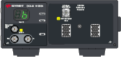
N1093A
Front Panel
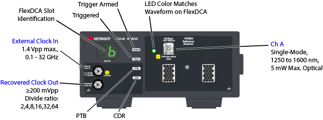
The front-panel Recovered Clock Out connector is activated by Option CDR.
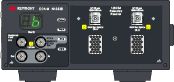
N1093B
Front Panel
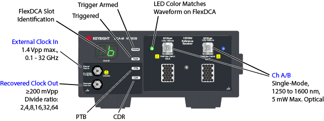
The front-panel Recovered Clock Out connector is activated by Option CDR.
Options
| Model/Option Number | Description | |
|---|---|---|
| N1093A | Single optical channel oscilloscope | |
| N1093B | Dual optical channel oscilloscope | |
| N1093A/B-CDR | Integrated Clock Recovery | |
| N1093A/B-CRX | Extended Clock Recovery Range | |
| N1093A/B-FS1 | Fast Sampling Rate | |
| N1093A/B-IRC | Impulse Response Correction | |
| N1093A/B-LOJ | Low Jitter Timebase | |
| N1093A/B-PLK | Pattern Lock Trigger Capability | |
| N1093A/B-PTB | Integrated Precision Timebase | |
| N1093A/B-C0C | Certificate of Calibration | |
| N1093A/B-UK6 | Commercial calibration certificate with test data | |
| N1093A/B-1CM | Single instrument rack mount kit | |
| N1093A/B-1CN | Dual instrument side-by-side rack mount kit | |
| N1093B-MFG 1 | N1093BB MFG Bundle Unit |
Option MFG is included on all N1093B units in N1093BB01A/02A/03A bundles.
Bundles
| Bundle | Description |
|---|---|
| N1093BB01A | Quad Channel DCA-M Bundle (two N1093B-MFG units, one with Option CDR) |
| N1093BB02A | Quad Channel DCA-M bundle (two N1093B-MFG units, neither with Option CDR) |
| N1093BB03A | Quad Channel DCA-M bundle (two N1093B-MFG units, both with Option CDR) |
The presence of option MFG indicates that an N1093B was purchased as as part of an N1093BB01A, N1093BB02A, or N1093BB03A bundle. N1093B modules that were not purchased as part of a bundle do not have option MFG.
How do you identify an N1093B as having option MFG? Option MFG is:
- Printed on the N1093B's rear-panel option sticker,
- Listed in FlexDCA's About dialog which is viewed by connecting the N1093B to FlexDCA and clicking Help > About, and
- Returned by the SCPI programming query
:SYSTem:OPTions?.
Key Concepts
- Input signal must meet the following requirements:
- 1250 nm to 1600 nm wavelength (single-mode).
- Symbol rate should be no greater than the selected reference filter. Reference filters are low-pass filters and not bandpass filters. Installed reference filters are listed on the N1093A/B's front panel under Filter Rates.
- The External Clock In input must meet the following requirements:
- Same symbol rate as the input signal or be a sub-rate clock for proper display of the input signal.
- Triggering occurs with any clock between 100 MHz and 32 GHz.
- Trigger setting can be Front Panel or Free Run only.
- Multiple DCA-Ms can be connected to FlexDCA. Delta time values between two channels cannot be compared because each DCA-M (and DCA-X if connected) uses an independent trigger.
- An DCA-X can simultaneously be connected to FlexDCA.
- Simulated waveforms can be displayed on FlexDCA.
- Use FlexDCA's remote programming commands to configure the N1093A/B.
Features
- Increased sampling rate.
- Perform optical transmitter compliance tests at standard symbol rates of 25.78 GBd (TDEC), 20.625 GBd, and 25 to 29 GBaud, depending on the installed filter options.
- Ability to perform eye-mask tests and measure eye diagram parameters including extinction ratio.
- Low-noise, high sensitivity calibrated reference receivers that are compliant to industry standard tolerances. The reference receivers are selected at the time of order and are noted as Filter Rates on the N1093A/B's front panel.
- Ability to perform basic oscilloscope mode measurements of pulses rather than eye diagrams (limited to patterns less than 2 ns in duration).
Aligning waveforms
Because a DCA-M’s acquisition system is independent of the DCA-X, the input waveforms may not align after an Auto Scale. This happens if your are using multiple DCA-Ms or a DCA-M with DCA-X receiver modules. To align the waveforms:
- Use Rapid Eye to align the channels. Rapid Eye is available on all N1000A and DCA-M scopes. Turn on Rapid Eye and the waveforms will align during an Auto Scale. Option 500 is the most convenient way to align the waveforms and maintains very fast throughput. Perform these steps:
- Click Setup > Acquisition to open the Acquisition Setup dialog.
- Select Enable Rapid Eye.
- Select Align Channels During Auto Scale.
- Manually delay the channels. If Rapid Eye is not installed as described above, you can manually add software delay to channels. Although this technique works, acquisition throughput will be reduced. For example, if channels 1A, 2A, and 3A are displayed, add software delay to channels 2A and 3A. The delays are referenced to channel 1A because Auto Scale aligns on the lowest numbered channel that is displayed. To add software delay,
- Click Auto Scale to autoscale the lowest numbered channel.
- For the remaining channels:
- Click Setup > Modules > Channels and select the channel.
- In the Setup dialog, click Advanced for the channel.
- Click Software Delay and enter the desired delay.
Rapid Eye is not available when using math functions or pattern lock.
Option IRC
Option IRC provides optical channel System Impulse Response Correction (SIRC) measurement and data files. These files provide an ideal channel response. SIRC data can be applied in the System Impulse Response Correction dialog. The SIRC correction data feature is a digital filter that is used to:
- Improve the response of module reference filters to more closely match an ideal receiver.
- Enable non-standard reference receiver rates or bandwidths.
- Increase the bandwidth of the channel by up to 50%.
- Ensures that an eye diagram will look identical between different modules.
SIRC correction data is unique to a specific module (serial number). Option IRC comes standard with N1093A/B DCA-M modules and N1030A/B, N1032A/B, and N1040A plug-in modules. You can purchase Option IRC ships for the N1092-series DCA-M modules.
Front-Panel Indicator Lights
| Indicator | Description |
|---|---|

|
Displays the FlexDCA extended module slot where the N1093A/B is installed. The number indicates the channel, which in this picture would be channel 6A. |

|
Green Trigger light indicates that the N1093A/B is being triggered. As with the DCA-X scope, this does not indicate that the trigger signal is synchronous with the channel input signal. The trigger must be set to Front Panel and not Module. |

|
Red Trigger light indicates that the clock input signal is missing. |

|
Trigger light off indicates that the N1093A/B channel is turned off or if FlexDCA is in single/stop acquisition mode. |

|
Trigger armed light. This light is red if FlexDCA is in single/stop acquisition mode. |

|
Channel indicator light. This light is next to the fiber-optic input connector. When on, the light indicates that the associated FlexDCA channel is turned on and that the waveform is displayed. The light is the same color as the displayed waveform. The Trig'd and Armed indicators do not light unless the channel is turned on. |
Remote programs previously developed using the N1000A FlexDCA interface can be leveraged directly to control an automated N1093A/B system. Measurement results are generally 50% faster with the new N1093A/B due to a significantly faster sampling rate.
Front-Panel Fiber-Optic Input
To avoid damaging the N1093A/B's front-panel fiber-optic connector, use proper connection techniques.
Click here to learn about fiber-optic connector care. Use caution as fiber-optic end surfaces are easily damaged due to improper cleaning techniques and repairs can be expensive.
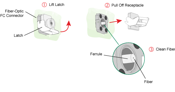
The front-panel fiber-optic input adapter can be removed and cleaned as shown in the following picture. To remove the fiber-optic adapter:
- Lift the receptacle latch as shown in the following picture.
- Carefully pull off the receptacle without touching the ferrule or fiber end.
Calibrations
The following calibrations are available for N1093-series modules within FlexDCA. Each is run from within FlexDCA's Calibration dialog.
- Vertical Calibration
- A vertical calibration allows you to calibrate the input channel's vertical response. This calibration is performed without an input signal.
- This calibration is located in the N109x tab on the Calibrations dialog.
- Dark Level Calibration
- Improves the accuracy of extinction ratio measurements by identifying internally generated offset (dark level) signals generated by external optical-to-electrical converters and removing them from the measurement. This calibration is performed without an input signal.
- This calibration is located in the Dark Level tab on the Calibrations dialog.
- User Optical Calibration
- A user optical calibration of the optical channel at any wavelength between 750 nm to 1650 nm. An external CW optical source is required.
-
- This calibration is located in the Optical tab on the Calibrations dialog.
- Factory Optical Calibration
- A factory calibration of the optical channel is performed at 850 nm, 1310 nm and 1550 nm. An external CW optical source is required.
- This calibration is located in the Optical tab on the Calibrations dialog.
- Timebase Calibration
- N1093-series modules have their own timebase. If multiple N1093-series modules are used or additional timebases are present, calibrations for each timebase will be listed in the Calibrations dialog. The calibration for each N1093A/B is clearly labeled by input channel.
- This calibration is located in the Timebase tab on the Calibrations dialog
Available Package Licenses
| Option | Description |
|---|---|
| RND | Research and Development Package license |
| MFG | Manufacturing Package license |