Extinction Ratio

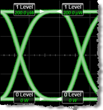
 The Eye mode Extinction Ratio is a measurement that represents how well available laser power is converted to modulation power. Mathematically it is the ratio of the logic one level to the logic zero level.
If very little power is used to transmit a zero level relative to the one level power, the ER will be high which indicates that the laser power is efficiently being used as modulation power.
Dark Level Calibration. The accuracy of the extinction ratio measurement can be affected by offsets, including the dark level, generated within the instrument electronics, typically following the photo diode. Offsets add to the incoming signal changing the values of the one and zero levels. This may decrease or increase the measurement result. To minimize extinction ratio measurement errors due to offsets, first perform a dark calibration.
The vertical scale setting affects the magnitude of the dark level offset. For best accuracy, perform the Dark Level calibration at the vertical scale at which you will make your measurement.
This measurement applies to NRZ waveforms and not to PAM4 waveforms. For PAM waveforms, use the Outer Extinction Ratio measurement.
Measurement Algorithm
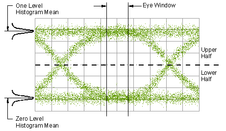
This measurement is made in a section of the eye referred to as the eye window boundaries. The default value for NRZ eye window boundaries is the central 20% of the symbol period (40% for Eye Boundary 1 and 60% for Eye Boundary 2 ). You can redefine the boundaries in the Eye Boundary tab of the Configure Base Measurements dialog. Histograms are constructed using the sampled portions of the eye diagram within the eye window boundaries. One histogram is comprised of data points from only the upper half of the eye diagram (one level). The second histogram is comprised of data points from the lower half of the eye (zero level). The histograms are analyzed to determine the histogram means.

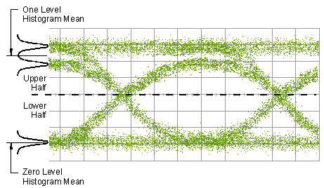
The following graphic illustrates how the histogram is constructed on an eye diagram that is pattern dependent. Pattern dependency is the behavior of a waveform as it is influenced by the preceding data pattern. For example, a logic level one that follows a logic level zero may have a different amplitude than a logic level one that follows a previously generated logic level one.In this example, there are two distinct one levels. A histogram is constructed using the data points from the one level and the histogram mean is determined.

Increasing the vertical scale sensitivity for a large eye diagram display typically yields a more accurate measurement. With a valid extinction ratio calibration, the extinction ratio measurement is computed and can be displayed in one of the three following formats:
Since the extinction ratio measurement is based on the histogram means of the one and zero levels, noise on the waveform typically does not have a significant effect on the accuracy of the measurement.
Configurable Measurement Parameters
This measurement is affected by the following settings (click Meas > Configure Base Meas.):
- Eye Boundary tab
- Extinction Ratio tab
To measure
- Select Eye/Mask Mode and set the vertical scaling to the desired level for the signal.
- Click Tools > Calibrations.
- Select Vertical Calibration for the required module.
- When the calibration is complete, select and run the Dark Level Calibration.
- Click Eye/Mask mode's Eye Meas tab.
- Click the Extinction Ratio button to run the measurement.
SCPI Command
:MEASure:EYE:ERATio