Bandwidth Limit
For DeEmbedding, and Deconvolution network setups, bandwidth limiting minimizes the effects caused by noise that occurs above the frequency where the signal is mostly attenuated. The application automatically sets the bandwidth limit, but you can manually set it, if needed. Normally you do not need to apply bandwidth limiting if you are adding loss (for example, applying the loss of a cable). However, if you are applying gain (for example, removing the loss of a cable), you may need to use this field.
To manually set bandwidth limiting, clear the Bandwidth Limit Auto checkbox. Select either a Gaussian or Sinc filter and set the filter's corner frequency. Bandwidth limiting is independent of waveform transformations and is applied to measured or simulated waveforms. It is implemented using a FIR filter that has a size (time span) determined by the filter's corner frequency.
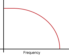
Ideally, you would like to transmit a signal through a channel component (cable, fixture, or probe) whose frequency response was flat over the full bandwidth of the signal, so that every frequency component of the signal was equally represented. In practice, the signal attenuates at higher frequencies as shown in this simplified graph.

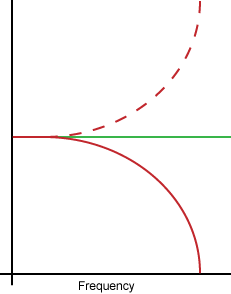
Some applications attempt to remove or correct this insertion loss in the channel using a correction transfer function, which becomes the inverse of the channel's insertion loss. This is represented by the dashed line in the following graph. The product of the peaked correction transfer function response and the channel response yields a flat frequency spectrum shown by the green line.

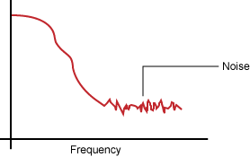
The following graph shows a more realistic frequency response graph. Above a certain frequency (or bandwidth) there is very little signal and mostly noise. Applying a correction using waveform signal processing as described above, may excessively amplify the noise. Bandwidth limiting minimizes this noise gain by attenuating the resulting waveforms above the frequency where there is mostly noise.
