Setting Up a Network
Use the De-Embedding Network Setup dialog to create de-embedding networks for your test setup. In the dialog, select from one of several preset configurations, such as Remove insertion loss of a fixture or cable. This displays a diagram within the dialog that is similar to the one shown in the following figure. Because these diagrams are interactive, you simply click on the diagram's different blocks to configuration the network. Network diagrams include several definition blocks as shown in the following representative diagram:
Click on an example circuit block types in this picture or click on the Circuit Block Types related-topics menu in this topic.
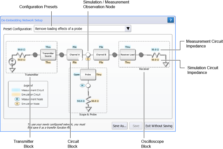
 After configuring your network, click Save As to save your network setup as a correction transfer function file.
The default user data folder for de-embedding network files is \De-Embedding Networks.
| Symbol | Description |
|---|---|

|
A measurement observation node that models the actual physical electrical circuit that produces the measured waveform. |

|
A simulated observation node that models a hypothetical electrical circuit that exhibits the electrical characteristics that you wish to measure. |

|
A white observation node that opens the Observation Node Setup dialog. Depending on the nodes position in the diagram, you can define it as a measurement node, simulation node, or both. |

|
A dark gray observation node can not be defined as a measurement or simulation node |

|
A blue text field identifies a measurement circuit block's type. In this example, an S-parameter file or an impedance. |

|
A bronze text field identifies a simulation circuit block's type. In this example, an S-parameter file or an impedance. |
|
|
S block that needs configuring to be complete. |
Circuit Block Setup Dialogs
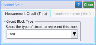 The Network Setup preset that you select will include a number circuit blocks shown in the following list. The Setup dialog for each of these circuit blocks is identical as shown here for a Channel Setup.
- Channel Circuit Block
- Transmitter Source Circuit Block
- Transmitter Channel Circuit Block
- Receiver Load Circuit Block
- Receiver Channel Circuit Block
- Probe Circuit Block
- Probe Channel Circuit Block
- Bridge Circuit Block
Circuit Block Types
In a circuit block dialog (such as the Channel Setup dialog), select the Circuit Block Type . For each circuit, first select the type of circuit in the drop-down list and then define the block. Depending on your network, one or more of the following circuit block types can be selected:
- Thru
- Open
- RLC
- File
- S-Parameter File
- Combination of Subcircuits
- Transmission Line (single-ended networks only)
- Dual 2-Port (differential networks only)
- Dual 2-Port Mixed Mode (differential networks only)