Configure ECal Adapters for DUT
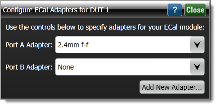
When performing the Calibration's Step 2, use the Configure ECal Adapters for DUT dialog when adapters are needed to be placed between the ECal ports A or B and the TDR head.
Adding adapters is accomplished using the Add New Adapter wizard, which steps through the following tasks:
- Naming the adapter so that it can be selected in this dialog.
- Entering is connector types.
- Measuring or manually entering the delay introduced by the Adapter.
If your test setup does not require an adapter to connect to the ECal module, you may skip this task. The following cases describe the different needs for adapters:
- Matching Connectors on Head, DUT, and ECal
- Matching Connectors on Head and DUT but not ECal
- Different Connectors on Head, DUT, and ECal
To define an adapter, run the Add New Adapter wizard that is included at the end of this topic.
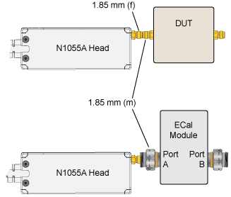
Case 1. Matching Connectors on Head, DUT, and ECal
If the TDR head mates to the DUT port and the ECal port, no adapter is required. Select None in the dialog for the Port adapter.
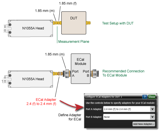
Case 2. Matching Connectors on Head and DUT but not ECal
If the TDR head mates to the DUT port but not the ECal port, an adapter is required. In the Add New Adapter wizard, add the information for this ECal adapter.
Because the TDR head connector requires an adapter to mate to the ECal connector, the following message is displayed near the top of the application until a compatible ECal adapter is assigned.
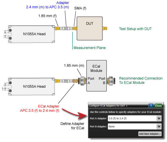
Case 3. Different Connectors on Head, DUT, and ECal
If the ports on the TDR head, DUT, and ECal module do not mate, an adapter is required to connect the head to the DUT and an additional adapter is needed to connect the head adapter to the ECal module. In Add New Adapter wizard, only enter the ECal adapter and not the DUT adapter.
Because the TDR head adapter's connector requires an adapter to mate to the ECal connector, the following message is displayed near the top of the application until a compatible ECal adapter is assigned.
To Add a New ECal Adapter
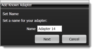
- Click Add New Adapter.
- Enter a name for your adapter. The name can be descriptive of the type, use, or other identification. If the adapter name already exists, you can overwrite the existing definition.
- Click Next.
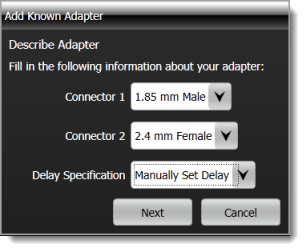
- Select the type of connector for Connector 1 and Connector 2.
- Select the Delay Specification: Measure Delay or Manually Set Delay.
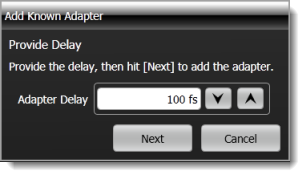
- If Manually Set Delay was selected, click Next. You will be prompted to enter a delay value in seconds.
- If Measure Delay was selected, connect your adapter to the TDR head. Do not connect anything to the adapter's other end. Click Next, and wait while the delay is automatically measured. When prompted, remove the adapter from the TDR head and click Next. A second measurement is made to complete the adapter definition.