Calibration Step 3
Timebase Options
The timebase options in the TDR Calibration Setup dialog allows you to control the timebase span.
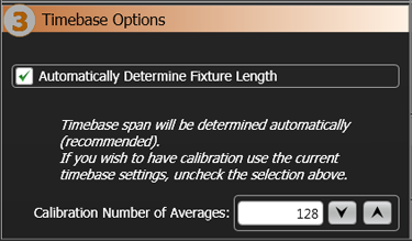
Automatically Determine Fixture Length
In most situations, it is best to leave Automatically Determine Fixture Length selected. A TDR calibration includes fixtures and cabling up to the DUT's input. In other words, the measurement's reference plane is moved to the end of the fixture. When the DUT is connected after the calibration, the time scale is automatically adjusted for a DUT response of any length. However, you can manually adjust the time span for the fixture length.
| On | Off |
|---|---|
|
|
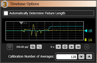
If automatic fixture length does not work
In some situations, FlexDCA may not be able to automatically determine the length of the fixture and, as a result, cannot perform a proper calibration. If this happens, clear the Automatically Determine Fixture Length setting as shown in the picture above, and use the displayed "live" window to confirm that the fixture's entire response is displayed. When manually adjusting the waveform on the displayed graph, the ![]() symbol marks the position measurement's reference plane before calibration. It marks the start of the fixture's response on the waveform, which is the TDR remote head's connector. Increasing the time span increases the distance over which impedance reflections can be viewed. Reducing the time span allows you to view more detail over a shorter distance. The following pictures show how to interpret example waveforms in the waveform viewport.
symbol marks the position measurement's reference plane before calibration. It marks the start of the fixture's response on the waveform, which is the TDR remote head's connector. Increasing the time span increases the distance over which impedance reflections can be viewed. Reducing the time span allows you to view more detail over a shorter distance. The following pictures show how to interpret example waveforms in the waveform viewport.
To adjust the fixture response in the window, perform the following steps:
| Step | Waveform |
|---|---|
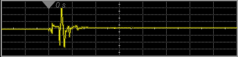
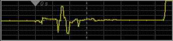
| 1. Observe the fixture's response as shown in this example of a two-port single-ended calibration for T11, T21, S11, and S21 measurements. Notice that the end of the fixture's response is difficult to identify. |
|
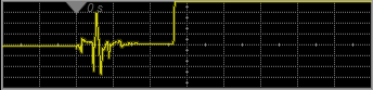
| 2. Remove the TDR head from the fixture's output port. This makes the location of the fixture's output easy to locate. |
|
| 3. Adjust the span to place the fixture's end near the right side of the window. |
|
Calibration Number of Averages
The recommended number of waveform averages during a TDR calibration is 128 to 256. By default 128 averages are taken. Increasing the number of averages decreases noise while increasing measurement accuracy. When making TDR/TDT measurements, averages can be decreased to 16 or 32. Increasing averages above the number used during calibration does not increase measurement accuracy. To set the number of a averages for measurements, click Setup > Acquisition Setup.