Calibration Step 1
Verify DUT Connections
Use this area of the TDR Calibration Setup dialog to verify the test setup. The picture graphically represents typical module-to-DUT connections. This is the first step of the calibration setup.
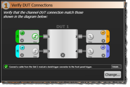
In this diagram, you can click on the following icons to change the configuration:
| Setup Control | Description |
|---|---|
|
|
Turns a TDR step on and off. You must turn on each step that will be active during some portion of your measurements. This control only appears for channels on N1055A TDR modules.
Turning TDR steps on determines which TDR and TDT responses (time domain parameters) and S-parameters are available for your measurements. The ability to use S-parameters requires Option 202. |
|
|
Opens the Configure DUT controls for defining custom names for the DUT ports. |
|
|
Opens the Channel Step controls for defining a TDR step's type, method, direction, amplitude, and rate. Normally, these setting are configured automatically and you will not need to change them. |
|
|
For TDR and TDR modules, turns the channel on and off.
If two or more TDR steps are simultaneously on, the channel waveforms include the effects of both step responses and are therefore not an accurate display of individual responses. Always view the time domain parameter waveforms to ensure that you are looking at an accurate waveform. |
Click Change to select a different DUT type or re-arrange the channel connections as allowed in the TDR Setup dialog.