:CHANnel:PROBe:DB
Command Syntax
:CHANnelN:PROBe:DB <dB>
<dB> is a double.
Where N identifies a specific channel in the form "<connection1-8>_<ch1-8>". With connection 1, the connection number part (that is, "1_") is optional, and you can simply use the channel number "<ch1-8>". For example, connection 4 channel 2 is CHANnel4_2.
Query Syntax
:CHANnelN:PROBe:DB?
Description
If the probe lets you set an attenuation/gain/dB value, you can use this command to set the value as a dB value.
The query returns the probe's attenuation/gain/dB setting as a dB ratio value.
You can also specify a probe's attenuation/gain/dB setting using the :CHANnel:PROBe:ATTenuation or :CHANnel:PROBe:GAIN commands, respectively. These commands give you three ways of interpreting the same setting.
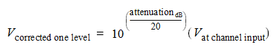
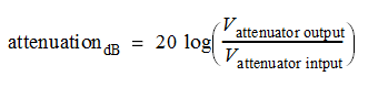
The relationship between decibels and voltage ratio is expressed by:
When entering attenuation in decibels, attenuation values less than 1:1 or gain values greater than 1:1 are positive dB values. Attenuation values greater than 1:1 or gain values less than 1:1 are negative dB values.
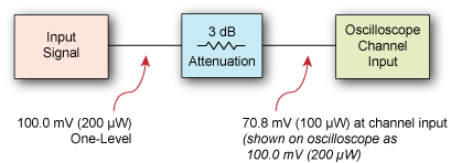
For example, if your test setup included 3 dB of attenuation, a signal with a 100.0 mV one level (before the attenuation) would be measured as 70.8 mV at the oscilloscope's channel input. However, after entering 3 dB (or 1.413:1 ratio) of attenuation compensation, the corrected oscilloscope measurement would read 100 mV.
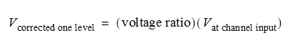
Based on an attenuation factor expressed as a voltage ratio, the conversion would be:
Based on an attenuation factor expressed in decibels, the conversion would be: