When the PXB is powered on, it displays the "1 Channel Generate" configuration, the most basic configuration in the Configuration Browser as the default. The PXB will only display configurations that the PXB’s baseband and I/O card option structure will support.
To turn on the PXB, press the front panel power hardkey.
Allow the PXB to boot and display the firmware.
Select the "Fade (ext in) 1 Channel" configuration from the Configuration Browser.
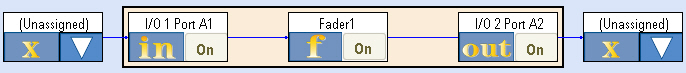
The block diagram for this selected configuration is displayed on the Block Diagram tab.
The PXB is designed to use a variety of external instruments to provide external inputs or received the output of the PXB. These external instruments can be controlled by the PXB firmware; however, the external instruments must be registered within the firmware prior to being available for use.
This example setup procedure uses the N5182A MXG For this example, we are calling out the Agilent MXG as the signal generator, however the Agilent E4438C ESG signal generator will also work well for the example.signal generator and the N9020A MXA signal analyzer as external instruments.
The registration process only needs to be performed once per instrument. If all of the instruments that you plan to use are already registered (see step 1), you may skip to the next section, "3. Assign External Instruments."
For this example, an Agilent N5182A MXG signal generator is being registered.
Click the External
Instrument Table tab to display the External Instrument Table. 
Illustration…
This illustration shows the External Instrument Table with that has been populated with several external instruments used with the PXB.
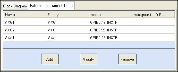
The External Instrument Table displays the external instruments that are currently registered with the PXB firmware. External instruments that can be registered are:
N5182A MXG Signal Generators (used at the output of the PXB)
E4438C ESG Signal Generators (used at the output of the PXB)
N5102A Digital Signal Interface Module (DSIM) (used at the input or output of the PXB)
N9020A MXA Signal Analyzer [used at the input of the PXB for (ext in) configurations]
The table displays the name, instrument type, address, and I/O Port (this is discussed more in the next step) of each registered external instrument. If no instruments are displayed in the table, then no instruments are currently registered.
Select the Add
button to start the registration process. This displays the Register External Instrument
dialog box.
Illustration…
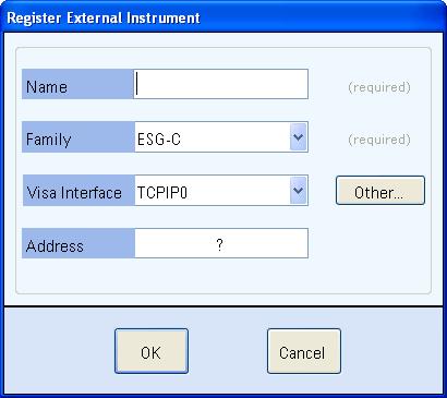
In the Name text box, enter "MXG1" or another name to describe your signal generator. For the remainder of this example, the signal generator is referred to "MXG1".
In the Family drop down list, select instrument family that describes the instrument's family. In this case, select MXG.
In the Visa Interface drop down list, select the interface that the PXB will use to communicate with the instrument (TCPIP0 = LAN or GPIB0 = GPIB).
In the Address text box, enter the address specific to the instrument that you are registering.
| As you proceed through this step, use the actual addresses for your instruments. |
Click the OK button to complete the registration. The External Instrument Table should now show the instrument that you just registered (an MXG, in this case).
Repeat steps 2 through 7 for the MXA signal analyzer required for this example configuration.
Click the Block Diagram tab to return to the configuration block diagram that was originally displayed.
External instruments must be selected and set up for the PXB.
In the Configuration Browser, ensure that the Fade (ext in) 1 Channel configuration is selected.
Review the block diagram.
You will see an I/O1 Port A1 block (this block is an input which connects to a signal analyzer), a Fader 1 block, and an I/O2 Port A2 block (this block is an output which connects to a signal generator). You will also see two (Unassigned) blocks which represent two unassigned blocks for two external instruments (the signal analyzer and the signal generator).
In the unassigned external instrument block at the
output, click the ![]() button to display the Assign
External Instrument dialog box.
button to display the Assign
External Instrument dialog box.
In the Assign
area of the Assign External Instrument
dialog box, select the MXG signal generator that you registered previously
from the Instrument drop down
list.
Illustration…
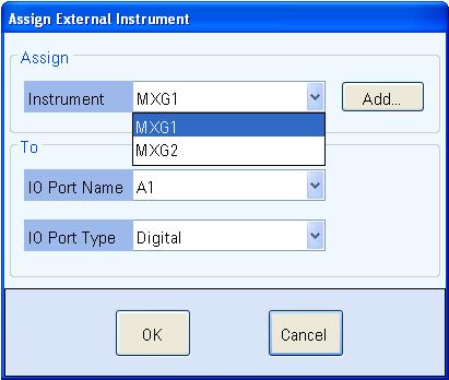
In the To area, leave the I/O Port Name field set to the default selection. Ensure I/O Port Type field is set to Digital.
The I/O Port Name field allows you to select any available I/O port.
The I/O Port Type field allows you to select from two types of I/O port connections, digital or analog, for the ESG or MXG signal generators. For additional information, refer to Assign External Instrument.
Click OK to return to the block diagram. Note that the external instrument block now displays the selected signal generator.
Repeat steps 3 through 6 to assign the signal analyzer to the unassigned external instrument block at the input.
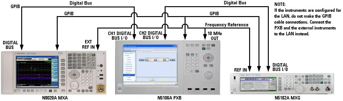
Connect the PXB to the signal analyzer and the signal
generator as shown.
Illustration…
Select the Load Configuration button to load the settings for each of the configuration blocks.
When the configuration is loaded, the Settings Browser replaces the Configuration Browser in the left panel of the user interface. Each block from the block diagram is also listed in the Settings Browser. You are now able to view and edit the settings for each block. Now we will set up the signal analyzer.
The PXB user interface provides basic control of the signal analyzer via the LAN/GPIB interface. The PXB and signal analyzer are also connected via the digital bus for waveform data transfer. Optimizing the MXA provides a procedure and discussion of how to maximize the MXA's dynamic range for use as an input to the PXB.
Open the settings for the assigned MXA signal analyzer. This can be done in one of two ways:
Select the MXA1 block in the block diagram
Select the MXA1 label in the Settings Browser
Notice that the MXA signal analyzer has one tab
that is displayed: General Settings
Illustration…
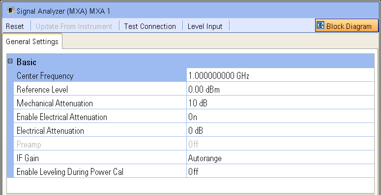
Review the General
Settings tab.
It provides some basic settings which allow control of the signal
analyzer from the PXB. For additional information about each setting,
refer to General Settings.
Use the Test Connection button above the tab to verify that PXB and the MXA are communicating with each other.
Note that there are also buttons that will preset the signal analyzer, update the PXB with the signal analyzer settings, and level the signal analyzer's input.
Return to the block diagram using the Block Diagram button.
Now we will set up the input I/O block. This block is the interface from the signal analyzer as it connects with the PXB.
Open the I/O settings for I/01 Port A1. This can be done in one of two ways:
Select the I/O 1 Port A1 block in the block diagram
Select the I/O 1 Port A1 label in the Settings Browser
Notice the four tabs that are displayed:
General Settings, Marker
Settings, Power Calibration Settings,
and Power Calibration Graphics
Illustration…
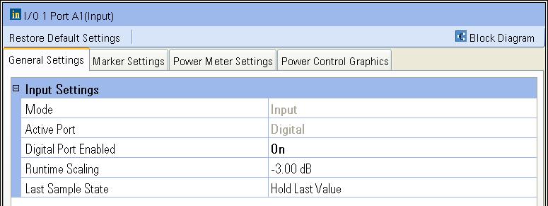
With the General Settings tab selected, ensure that the Digital Port Enabled is set to On.
Review the remaining settings on the General Settings tab.
Select the Marker Settings tab to review this tab's settings. You may refer to the Marker Basics tutorial for additional information regarding markers.
Select the Power Calibration Settings tab to review this tab's settings. The Power Calibration Graphics tab provides a graphical description of some of the power control settings.
Select the Block Diagram button to return to the block diagram.
Navigating the Fader block is slightly different and a little more complex than other configuration blocks. You will see that fading has two areas for setup: Master Setup and Fader Paths. For this reason, the fading procedure is organized in three parts:
The Fader block has two areas, Master Setup and Fader Paths. The Master Setup interface is similar to the other block interfaces that we have explored. The Fader Paths interface is a table that defines each of the fading paths.
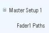
Open the Master
Setup settings for Fader1
by selecting Master Setup 1 from
the Settings Browser. If necessary,
expand the settings beneath the Fading
label by selecting the ![]() icon. Note that the Fader
Paths label is beneath the Master Setup label as shown.
icon. Note that the Fader
Paths label is beneath the Master Setup label as shown.
Illustration…
Notice that Master Setup has a Fader Setup tab. If
you are using a configuration that has a Master
Setup with more than one Fader block, such as 2 Channel Fade (ext
in), there is also a Correlation
tab (highlighted in the illustration).
Illustration…
Note that when a configuration's Master
Setup has more than one Fader block, multiple Fader settings are
displayed on the Fader Setup tab as well. This area is also highlighted
in the illustration.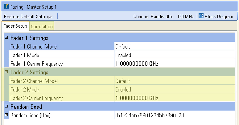
With the Fader Setup tab selected, review this tab's settings.
When you use a configuration that has a Master Setup with more than one Fader block, you can access the Correlation tab to edit the correlation table defining the degree of correlation for the paths between the Fader blocks.
After reviewing the Master Setup, open the Fader1 Paths table by selecting the Fader1 Paths label in the Settings Browser.
Review the Fader1 Paths table.
Illustration…
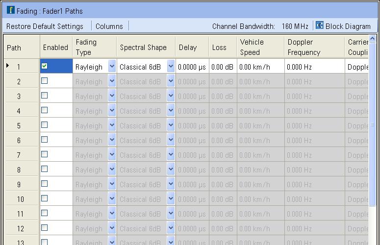
By scrolling down, you will notice that there are 24 rows representing each of the PXB's maximum of 24 paths. By scrolling across the table from left to right, you can see there are a variety of settings used to define each path.
Setting up the Fader block can be as easy as selecting the appropriate fading model that you are using from a list of standard technologies.
With Fading expanded in the Settings Browser, select Master Setup 1 to view the Master Setup settings.
Select Fader 1
Channel Model to display the drop-down ![]() button at the right edge of its settings
cell. Then select the drop-down button to display a list of the available
fading channel models.
button at the right edge of its settings
cell. Then select the drop-down button to display a list of the available
fading channel models.
For this example of the Fader
1 Channel Model setting, select W-CDMA,
then select Base Station, and
then select Moving Propagation.
Illustration…
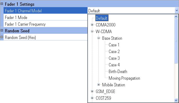
As you can see, there are many channel models included in the PXB to choose from.
Once you have selected Moving
Propagation, ensure that Fader1
Paths is displayed below Master
Setup 1 in the Settings Browser.
If not, expand the Master Setup 1
using the ![]() icon to display it.
icon to display it.
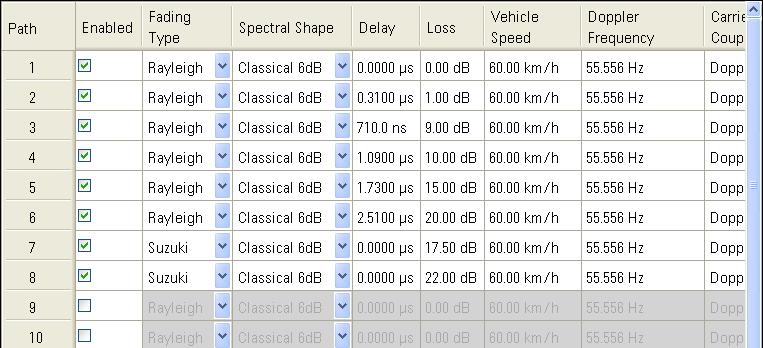
Select Fader 1
Paths to display the number of paths, the fading type, the spectral
shape, the delay values, and a variety of other variables – which are
all based on the standard for the selected channel model.
Illustration…
These channel model variables are displayed in tabular format This table is complex and can list approximately 20 variables across the ”r;X-axis”, although just a few can be seen without scrolling. All of the available paths are listed along the ”r;Y-axis”.
Select the Master Setup 1 from the Settings Browser to return to the Fader Setup settings.
Having just set up the Fader block by selecting a channel model from a list of standard technologies, we will look at using one of these standards and customizing it to fit any specific fading needs you may have.
Change the Fader 1 Channel Model setting from the previous selected W-CDMA, Base Station, Moving Propagation standard by selecting Mobile WiMAX, then Vehicular A(60 kph) in the drop-down list, as in step 3 of the Basic Fading Setup procedure above.
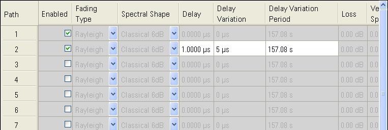
Select Fader 1 Paths to display the number of paths and all of the other variables for the selected channel model.
It’s easy to see that this new standard has different properties than the one we looked at previously.
Select the Enabled check boxes for paths 7 and 8 so they are both checked. You have just added two paths to the channel model.
For paths 7 and 8, click the Fading Type drop-down button and select Suzuki for each path.
Enter "17.50 dB"
in the Loss column for path 7
and enter "22 dB" in the Loss
column for path 8. These are both arbitrary values. You could enter a
meaningful value for your test requirements.
Illustration…
We have just added channels and changed settings to show that you can customize your Fader setup by manually adjusting the channel properties to meet your specific needs. These types of changes may be made to any of the attributes of the standard settings definitions. You have two different ways to set up fading: From Standard and Custom.
Return to the block diagram.
The output I/O port is used as the output interface to an external instrument (either a signal generator or an N5102A Digital Signal Interface Module) at the output of the PXB. The output I/O Block has its own settings that are customized for the output. For additional information, refer to the I/O Port Setup tutorial.
Open the I/O Port settings for I/O2 Port A2. This can be done in one of two ways:
Select the I/O2 Port A2 block in the block diagram
Select the I/O2 Port A2 label in the Settings Browser
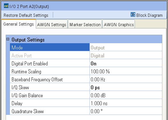
Notice the four tabs that are displayed: General
Settings, AWGN Settings,
Marker Selection, and AWGN
Graphics.
Illustration…
The following is a quick review of how each of the tabs can influence the output of the PXB.
Review the General Settings tab.
The General Settings tab provides information about the I/O port and can be used to make changes to the I/O port. You will notice that the Mode setting is a read-only entry that displays Output indicating that this I/O port is being used as an output I/O.
Select the AWGN Settings tab to review this tab's settings. This tab is used to add and control Additive White Gaussian Noise (AWGN) to the output signal at the I/O port. The AWGN Graphics tab provides a graphical description of some of the AWGN settings.
Select the Marker Settings tab to review this tab's settings. For additional information, you may also refer to the Marker Basics tutorial.
The I/O output block can pass the existing markers from the input source (the baseband generator or I/O input block) or can dynamically generate new markers based on the waveform present at the I/O output block. Markers that are generated from an output I/O block that is receiving a single-input waveform are merged with the waveform as it was received. Therefore, if the original waveform has had fading or interference added, the degraded waveform is used to generate these markers. This is important to note because dynamic markers use the values of the waveform samples to determine when markers are generated.
Any output I/O markers will override markers previously embedded in the original waveform file or generated by a user-created marker file or input I/O block.
Return to the block diagram.
The PXB provides direct control of several of the signal generator settings. These settings include the output frequency, the output amplitude, and the internal marker routing and more. It does not provide control of all the signal generator settings.
Open the MXG settings for MXG1, the signal generator that we have assigned as the external instrument for this configuration. This can be done in one of two ways:
Select the MXG1 block in the block diagram
Select the MXG1 label in the Settings Browser
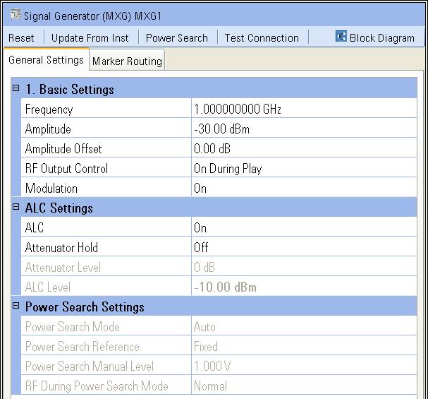
Notice that
this external instrument has two tabs that are displayed: General
Settings and Marker Routing
Illustration…
The following is a quick review of how each of the tabs can be used to control the signal generator from the PXB.
| The values shown in the display not reflect the actual signal generator state unless an update to instrument (Update To Inst) or an update from instrument (Update From Inst) is performed. The PXB uses the actual values from the signal generator when necessary. |
Select the Preset button to preset the signal generator.
Review the General Settings tab.
The General Settings tab
is comprised of three categories:
Basic Settings which provides control of very basic signal generator settings.
ALC Settings which provides control of the signal generator’s Automatic Level Control (ALC) and attenuator circuitry.
Power Search Settings which provides control of the signal generator’s power search function when a power calibration is performed.
Set the RF Output parameter to On so the signal generator’s RF Output connector will be on when the waveform is played.
Set the ALC parameter to Off so the signal generator’s ALC circuitry will not interfere with the power calibration when it is performed.
Select the Update to Inst button to pass the settings to the signal generator.
Select the Marker Routing tab to review this tab's settings. This tab allows you to set up the markers to control the Pulse/RF Blanking and the ALC Hold features. For additional information, you may also refer to the Marker Basics tutorial.
Return to the block diagram.
Once the PXB configuration is set to meet your test needs, you can simply calibrate the system power and play the signal from the connected signal analyzer via its digital bus through the input I/O block, the Fader block, and the output I/O block to the connected signal generator via its digital bus.
Power calibration occurs automatically by default.
If you want manual control of power calibration,
select Maunal in the System
> Calibration > Power Calibration menu, then select the Calibrate Power button to perform the
power calibration based on the input I/O block's Power Meter Settings
and the output I/O block's AWGN Settings.
More information
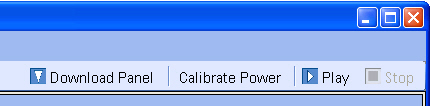
Select the Play button to start playing the signal.
When you wish to stop playing the waveform, select the Stop button.
To save the configuration and its settings, select Save from the File menu.
To recall the configuration and its settings, select Recall from the File menu.