:CMODe Subsystem
The :CMODe subsystem commands control common-mode reflection waveforms in TDR/TDT mode. Common-mode waveforms are most useful when the TDR setup is configured using the TDR Basic Control setup dialog rather than the TDR DUT Based Setup dialog. With the TDR DUT Based Setup:
- You can configure both differential and common mode traces to provide mixed stimulus S-parameters.
- Time-domain parameters are not available.
Common-mode waveforms are only available in TDR/TDT mode.
To Use the Common-Mode Commands
- Install a TDR module in the DCA-X mainframe.
- Place FlexDCA in TDR mode.
- On FlexDCA's menu, click Setup > TDR Basic Control (
:TDR:EXPerience BCONtrolcommand). - In the TDR Setup dialog for basic control, for the TDR Stimulus Mode select Differential (
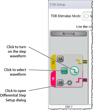
:TDR:AMODE DIFFerentialcommand). - In the TDR Setup dialog, click the gear icon shown in the following picture to open the Differential Step Setup dialog. In the dialog, select Common Mode. Click to select the waveform and turn on the step. Close the dialog.
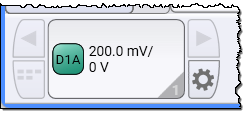
- Click the TDR module tile on the channel 1 to open the Module Setup dialog.
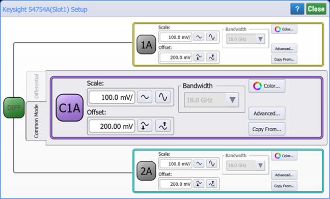
- In the Module Setup dialog, select the Common Mode tab. The
:CMODeSCPI subsystem controls the settings that are located in the Common Mode tab.
Waveform Identification
In the :CMODe command syntax, common-mode waveforms are identified by the associated module slot number (from 1 to 4). For example, the following command sets the color of the common-mode waveform of an N1055A TDR module installed in slots 1.
:CMODe1A:COLor TCOLor8
Traditional modules take up two module slots, either slots 1 and 2 or slots 3 and 4. For these type of modules, the common-mode waveform is identified using the number for the left-most occupied slot. For example, :CMODe1A or :CMODe3A, respectively. Single-slot modules could have two channels. In this case, the common-mode waveform of a module installed in slot 4 would be identified as :CMODe4. Also, when FlexDCA is configured with a simulated extended module, one-slot simulated modules are available that have two channels. The following table show several examples of common-mode waveform identification.
| Module Type | Installed Slots |
Source Channels for Differential Waveform |
Differential Channel Waveform Identification |
|---|---|---|---|
| Traditional Two-Slot, Dual Channel (for example, 54754A) |
1 & 2 | 1A and 2A | :CMODe2A
|
| 3 & 4 | 3A and 4A | :CMODe3A
|
|
| Simulated or Future Single-Slot, Dual Channel |
1 | 1A and 1B | :CMODe1A
|
| 2 | 2A and 2B | :CMODe2A
|
|
| 3 | 3A and 3B | :CMODe3A
|
|
| 4 | 4A and 4B | :CMODe4A
|
This subsystem Requires FlexDCA revision A.04.00 and above.
Example Commands
:SYSTem:MODE TDR
:TDR:EXPerience BCONtrol
:TDR:AMODE DIFFerential
:TDR:STIMulus:CHAN1A:TYPe CMODe
:TDR:STIMulus:CHAN1A:STEP ON
:CMODe1A:DISPlay ON
:CMODe1A:TCOLor 7