Creating Limit Line XML Files
Limit Line Test files are XML files that you design using an ASCII editor such as Notepad++. Limit Line Test files define one test which can have up to 16 limit lines with each line defining up to 2048 points. Of course, it is unlikely that you will ever need a Limit Line Test with this many points.
The following example shows a very simple file, as it defines a test with only one upper limit line having just two points.
<CLimitLineTestData Name="Upper Limit Line">
 <CLimitLine Name="top rail" IsMaxLine="True">  <!-- Define Upper Limit Line -->
  <CLimitLinePoint X="0" Y="150e-03" />  <!-- Define one point of the line -->
  <CLimitLinePoint X="500e-12" Y="150e-03" />  <!-- Define second point -->
 </CLimitLine>
</CLimitLineTestData>
Notice that the X and Y values in the above example are unitless. On loading, the limit line's X and Y values are interpreted in the current content window's horizontal and vertical units, as shown in the following table.
| Window Type |
Oscilloscope Mode |
TDR Mode |
Interpretation of X and Y Axis Values | Window Content |
|---|---|---|---|---|
| Waveform | ♦ | ♦ | Y-Axis: Volts or Watts (linear scale) X-Axis: seconds |
Channels, differential channels, most functions, waveform memory, and eye/mask memory. |
| Freq-Mag | ♦ | ♦ | Y-Axis: dBV or dBm (logarithmic scale) X-Axis: seconds or Hertz |
Output of FFT math function and TDR/TDT S-Parameters |
| GrpDelay | ♦ | ♦ | Y-Axis: seconds X-Axis: Hertz |
Output of FFT math function and TDR/TDT S-Parameters |
| Phase | ♦ | ♦ | Y-Axis: phase (°) X-Axis: Hertz |
Output of FFT math function and TDR/TDT S-Parameters |
| Time-Ohms | ♦ | Y-Axis: Ohms X-Axis: Time |
TDR/TDT T-Parameter Responses | |
| Time-Volts | ♦ | Y-Axis: Volts X-Axis: Time |
TDR/TDT T-Parameter Responses | |
| Time-% | ♦ | Y-Axis: % X-Axis: Time |
TDR/TDT T-Parameter Responses |
Limit Line Tests are defined using three XML elements. There is no XML declaration. The three XML elements have the following hierarchy. Click on the elements to learn about their use.
Rules and Restrictions
- XML is case sensitive. For example, the attribute declaration Name="Upper Limit Test" is valid, whereas name="Upper Limit Test" is not.
- The <CLimitLineTestData> root element, which delares a Limit Line Test, must begin and close every file and there can only be one instance of this element. Additional instances of this element are ignored.
- From 1 to 16 limit lines can be defined in a file. Each limit line can be declared as an upper (maximum) or lower (minimum) line and, if undeclared, defaults to an upper (maximum) line. Limit Line names are optional.
- Limit Line definitions must include a minimum of two points. The maximum number of points is 2048.
- Points within a limit line definition must be defined in ascending order of X values. The only exception is when two consecutive points have the same X value, as when creating a vertical section of the limit line. Any number of adjacent points can have the same Y value.
- The maximum number of points allowed in a Limit Line Test file is 32,768 (16 limit lines at 2048 points each).
- Use the .lltx file name extension when naming your file.
The XML elements that are used to define limit lines are not the same as the elements used for creating masks in Eye mode.
Comments
Don't forget to add comments to your Limit Line Test files. To create a comment use the <!-- and --> delimiters as shown in the following example. Comments can be on their own line, at the end of a line, or extend over several lines.
<CLimitLineTestData Name="Limit Line Test">
 <!-- Define Upper Limit Line -->
 <CLimitLine Name="top rail" IsMaxLine="True">
  <CLimitLinePoint X="0" Y="150e-03" />  <!-- Define the first point -->
  <CLimitLinePoint X="500e-12" Y="150e-03" />  <!-- Define another point -->
  <CLimitLinePoint X="600e-12" Y="400e-03" />  <!-- Define another point -->
  <CLimitLinePoint X="900e-09" Y="400e-03" />  <!-- Define another point -->
 </CLimitLine>  <!-- Finish the line -->
</CLimitLineTestData>
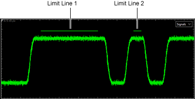
Limit Line Test Example 1.
This example shows two separate limit lines with a gap between them. The two lines have the same amplitude, but because of the gap, they must be defined as two separate limit lines.
| Displayed Limit Lines | Limit Line Test File |
|---|---|
|
<CLimitLineTestData Name="Upper Limits"> <CLimitLine Name="Limit Line 1" IsMaxLine="True"> <CLimitLinePoint X="880e-12" Y="60e-03" /> <CLimitLinePoint X="1175e-12" Y="60e-03" /> </CLimitLine> <CLimitLine Name="Limit Line 2" IsMaxLine="True"> <CLimitLinePoint X="1360e-12" Y="60e-03" /> <CLimitLinePoint X="1400e-12" Y="60e-03" /> </CLimitLine> </CLimitLineTestData> |
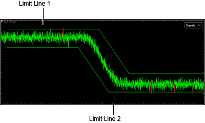
Limit Line Test Example 2.
This example shows two methods for creating the same two limit lines and the affect of an applied horizontal offset. Horizontal offset is always applied to the entire contents of a Limit Line Test file. The first method defines both limit lines in the same file. Any applied horizontal offset to the Limit Line Test is applied simultaneously to both limit lines. The second method defines each limit line in a separate Limit Line Test File. With this method, you can apply horizontal limit line offset separately to each limit line.
| Displayed Limit Lines | Limit Line Test File |
|---|---|
|
Limits lines defined in one Limit Line Test file. <CLimitLineTestData Name="Lower and Upper Limits"> <CLimitLine Name="Limit Line 1" IsMaxLine="True"> <CLimitLinePoint X="530e-12" Y="60e-03" /> <CLimitLinePoint X="620e-12" Y="60e-03" /> <CLimitLinePoint X="650e-12" Y="-25e-03" /> <CLimitLinePoint X="730e-12" Y="-25e-03" /> </CLimitLine> <CLimitLine Name="Limit Line 2" IsMaxLine="False"> <CLimitLinePoint X="530e-12" Y="25e-03" /> <CLimitLinePoint X="600e-12" Y="25e-03" /> <CLimitLinePoint X="630e-12" Y="-60e-03" /> <CLimitLinePoint X="730e-12" Y="-60e-03" /> </CLimitLine> </CLimitLineTestData> |
Limits lines defined in two Limit Line Test files. File 1:
<CLimitLineTestData Name="Upper Limit">
 <CLimitLine Name="Limit Line 1" IsMaxLine="True">
  <CLimitLinePoint X="530e-12" Y="60e-03" />
  <CLimitLinePoint X="620e-12" Y="60e-03" />
  <CLimitLinePoint X="650e-12" Y="-25e-03" />
  <CLimitLinePoint X="730e-12" Y="-25e-03" />
 </CLimitLine>
</CLimitLineTestData>
|
|
File 2:
<CLimitLineTestData Name="Lower Limit">
 <CLimitLine Name="Limit Line 2" IsMaxLine="False">
  <CLimitLinePoint X="530e-12" Y="25e-03" />
  <CLimitLinePoint X="600e-12" Y="25e-03" />
  <CLimitLinePoint X="630e-12" Y="-60e-03" />
  <CLimitLinePoint X="730e-12" Y="-60e-03" />
 </CLimitLine>
</CLimitLineTestData>
|
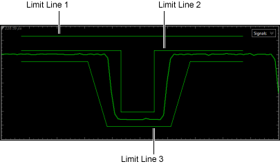
Limit Line Test Example 3.
This example shows that multiple upper (or lower) limit lines can be defined in the same Limit Line Test file. The example also shows a limit line that includes a vertical section.
| Displayed Limit Lines | Limit Line Test File |
|---|---|
|
<CLimitLineTestData Name="3 Limit Lines"> <CLimitLine Name="Limit Line 1" IsMaxLine="True"> <CLimitLinePoint X="300e-12" Y="70e-03" /> <CLimitLinePoint X="1100e-12" Y="70e-03" /> </CLimitLine> <CLimitLine Name="Limit Line 2" IsMaxLine="True"> <CLimitLinePoint X="300e-12" Y="50e-03" /> <CLimitLinePoint X="660e-12" Y="50e-03" /> <CLimitLinePoint X="660e-12" Y="-35e-03" /> <CLimitLinePoint X="780e-12" Y="-35e-03" /> <CLimitLinePoint X="780e-12" Y="50e-03" /> <CLimitLinePoint X="1100e-12" Y="50e-03" /> </CLimitLine> <CLimitLine Name="Limit Line 3" IsMaxLine="False"> <CLimitLinePoint X="300e-12" Y="35e-03" /> <CLimitLinePoint X="540e-12" Y="35e-03" /> <CLimitLinePoint X="610e-12" Y="-55e-03" /> <CLimitLinePoint X="840e-12" Y="-55e-03" /> <CLimitLinePoint X="910e-12" Y="35e-03" /> <CLimitLinePoint X="1100e-12" Y="35e-03" /> </CLimitLine> </CLimitLineTestData> |