Create Limit Line Test from Waveform
The Create Limit Line Test from Waveform dialog automatically draws maximum and minimum limit lines at specified offsets from a displayed waveform. Use it to quickly create accurate limit lines for testing waveforms against a golden device.
| Field | Description |
|---|---|
Select Source Waveform: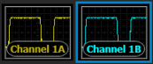 |
If more than one waveform is displayed, click the waveform from which you want to derive the limit lines. In this picture, the Channel 1B waveform is selected. If you find that additional waveforms on the display confusing, temporarily turn the unneeded channels off. In Oscilloscope mode, limit lines can be placed on channels and memories. In TDR/TDT mode, limit lines can be created for T-Parameter waveforms and S-Parameter waveforms (viewed in Waveform Content Windows) and on S-Parameter memories. |
| Test Name: | Enter a name that will identify your limit line in the Limit Line Test dialog and the Limit Lines panel. |
| Number of Points: | Enter the number of points used to draw each limit line. The default number is 100. |
| Optimally Spaced Points and Evenly Spaced Points |
When Optimally Spaced Points is selected, applies curve fitting to the limit lines. Curve fitting often improves the shape of limit lines that are drawn using relatively few points. |
| Limit Line Waveform Lock Margins | When selected, the top and bottom lines are locked relative to each other. Move one line and the other line also moves. |
| Top Line Name: Bottom Line Name: |
Enter the names used to identify each of the two created limit lines in the Limit Line Test dialog. By default, the two created limit lines are named Top Line and Bottom Line. |
| X Margin: Y Margin: |
Entered offsets in the current amplitude units (Y Margin) and the current horizontal scale units (X Margin). The offsets affect the spacing between the waveform and the drawn limit lines. |
|
Redraws the limit lines. Use this feature whenever the source waveform has changed for any reason or because you have changed FlexDCA's horizontal scaling. |

|
Click to create the limit lines and to display the Limit Line Test dialog.
NOTEThe limit lines are loaded into FlexDCA but are not saved to a file. To save your limit lines, click the Save As button in the Limit Line Test dialog. |
Move the dialog so that it does not cover the displayed waveform. Now you can view in real time affects on the displayed limits lines while changing the settings in the dialog.
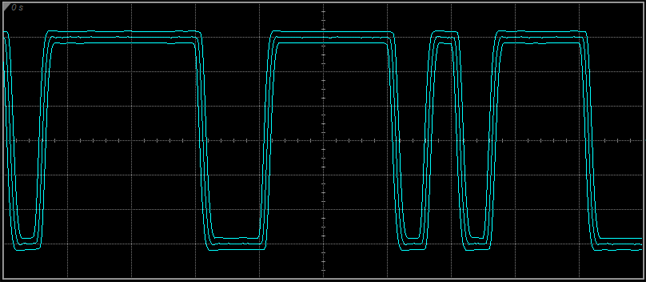
Example of Limit Lines Derived from Waveform
Creating the Limit Lines
In the following procedure, steps 2 and 3 are not required but are included to illustrate how to produce limit lines definitions that result in fewer points and smoother lines.
- Display a waveform with the desired amplitude and time scale.
- Click Setup > Acquisition Setup. On the Smoothing tab, select Average and enter a large number of waveforms to average. For example, enter 4096.
- On the dialog's Waveform tab, reduce the number of Waveforms/Sample to a number that results in good waveform fidelity with fewer points. The waveform shown above was produced using 400 waveform points with 4096 averages. Close the dialog.
- On the menu, click Tools > Limit Line Test Editor. Move the dialog so that you can see as much of the displayed waveform as is possible.
- Select Create New (Waveform).
- In the Limit Line Waveform Creation Editor dialog, accept the defaults or make any desired selections.
- Click Create.