Creating Masks
When an available standard mask is not suitable for your application, you can create a new custom mask using an ASCII editor, such as Microsoft® Notepad. Or, you can edit a copy of any of the available standard masks. FlexDCA mask files (*.mskx) use an XML-based format, and you build your XML file using the elements documented in this topic. If you're not familiar with writing XML, there are many widely available introductory books as well as web sites that you can consult. This topic is not intended to teach XML.
The XML elements that are used to define masks are not the same as the elements used for creating limit lines in Oscilloscope and TDR/TDT modes.
XML Elements and Hierarchy
Using a text editor, open any FlexDCA mask file. If you are familiar with XML, you'll notice that mask files do not include an XML declaration at the top of the file. XML is case sensitive. All content in mask files must be enclosed by an element. Each element must begin with an opening tag and end with a closing tag. Opening tags are enclosed in < > characters, for example, <Mask>. Closing tags are enclosed in </ > characters, for example </Mask>. <Mask> is the root element, and it is a required element that must begin every file.
The following list shows the XML elements and their hierarchy, which allows you to visualize that, for example, <Polygon> is the child of <Region> and the parent of <Vertex>. Click on the elements to learn about their use.
- <Mask>
- <Title>
- <Standard>
- <Date>
- <DataRate>
- <Region>
- <Polygon>
- <Vertex>
- <Setup>
- <MaskAlignMethod>
- <MaskYAlignMethod>
- <MaskAlignmentOptimize>
- <MaskX1>
- <MaskYTrack>
- <MaskScaleMode>
- <MaskY1>
- <MaskY2>
Comments
You can add comments to your mask files to document the mask's use and construction. To create a comment use the <!-- and --> delimiters as shown here:
<!-- This is my comment! -->Comments can be on their own line, at the end of a line, or extend over several lines.
- <Mask>
- <Title>10GbE 10.3125</Title>
- <Standard>Ethernet</Standard>
- <Date>05/01/2002</Date>
- <DataRate>1.031250e+010</DataRate>
- <!-- Center Mask Region -->
- <Region Number="1"> <!-- Mask Region 1 -->
- </Region>
- </Mask>
Mask File Preamble
The <Mask> root element should be followed by three metadata elements and the <DataRate> element. The three metadata elements are <Title>, <Standard>, and <Date>. The following example shows the first five lines of any mask file:
- <Mask>
- <Title>10xGB Ethernet</Title>
- <Standard>Ethernet</Standard>
- <Date>Oct 23, 2010</Date>
- <DataRate>1.250000e+010</DataRate>
- </Mask>
Creating Mask Violation Areas
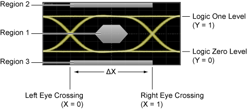
Each mask violation region is defined with the <Region> element. The following picture shows a mask that has three regions. Each region in a mask must define three polygons using three separate <Polygon> elements. One <Polygon> draws the standard polygon, one <Polygon> draws the maximum mask-margin polygon, and one <Polygon> draws the minimum mask-margin polygon.
The <Vertex> element is used to define the X and Y coordinates of each vertex of a polygon. A polygon must have at least three vertices. A relative coordinate system is used based on an eye diagram's zero level, one level, and crossing points. For more information, refer to the <Vertex> element topic.
There are no elements for defining mask margins.
Mask File <Setup> Element
Every mask file ends with the <Setup> element. The available child elements configure the mask settings of the Mask Test Scaling dialog and the Configure Measurements dialog's Mask Test tab.