Observation Node
Instrument:
N1000A
N109x
UXR Scope
Flex Apps:
FlexDCA
FlexRT
Meas. mode:
Scope
Eye
Jitter
Package License:
L-RND
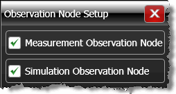
Use the Observation Node Setup dialog to configure an observation nodes. Observation nodes indicate circuit locations that represent the:
- Measured Waveform. This is the waveform before de-embedding has been applied. The measurement circuit models the actual physical electrical circuit that produced the measured waveform.
- SimulatedWaveform. This is the circuit location that de-embedding allows you to simulate. The simulation circuit models a hypothetical electrical circuit that exhibits the characteristics that you want to measure.
 Observation Node symbols on your de-embedding network appear either dark gray or white (as shown in this picture). Click on a white observation node to open the Observation Node Setup dialog. Depending on a white node's position in the diagram, you can select it as a measurement node
  , simulation node
  , or both. Dark gray observation nodes can not be defined as a measurement or simulation node.