AWG Basic Setup
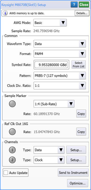
After making a Flex-on-SFP connection, click the AWG tile on the bottom tray to open the dialog.
AWG Basic Mode
Select from either the Basic or Advanced AWG modes before making any other selections in this dialog. This topic describes the dialog's settings in Basic mode. A separate topic describes the available Advanced mode settings. Click here to learn about the differences between the Basic and Advanced AWG modes.
Common Settings
Changes that you make to the Common dialog area apply to all AWG channels.
Waveform Type. Selects either a waveform generated by waveform parameters sent to the AWG (Data) or downloaded from a FlexDCA waveform file (Load from File). Downloaded FlexDCA waveform files must be an ASCII Pattern Format Waveform Files (.csv) format for an NRZ or PAM4 waveform. After selecting Load from File, click Browse to load the file. You can also load an optimized waveform file that is created when you click Optimize.
Format (Data Waveform type only). Selects a waveform coded as NRZ or PAM4. This selection is not displayed when the Waveform Type has been selected to be Load from File.
Symbol Rate. For Data Waveform Types, selects the symbol rate for the channels. For Load from File Waveform Types, this field will be populated with a symbol rate if the file contains a full pattern waveform and you can not edit the value. If the file contains a partial pattern waveform, enter the symbol rate in this field. For channels that will be configured as a Clock, you can set the clock to a sub-rate of this symbol rate using the Clock Div. Ratio field.
Pattern. This field is displayed when the Waveform Type is selected to be Data. Selects the pattern from the drop-down list.
Pattern Length. This field is displayed when the Waveform Type is selected to be Load from File. The field will be populated with a pattern length if the file contains a full pattern waveform and you can not edit the value. If the file contains a partial pattern waveform, enter the pattern length in this field.
Clock Div. Ratio. Select the ratio between the data and the clock waveforms.
Relationship between symbol rate, pattern length, and clock divide ratio.
Due to the finite memory of an AWG and the constraint of waveform wrapping, the maximum symbol rate that you can set is approximately one half of the AWG's sampling rate. In addition, reducing the sample rate reduces the maximum available pattern length. The available clock divide ratios also depend on the symbol rate and pattern length. The best way to view these dependencies is do the following:
- Make a FlexDCA-to-AWG connection and open this dialog.
- In the dialog, select the highest Symbol Rate.
- While using a scroll-wheel mouse, hover the mouse cursor over the Symbol Rate field and scroll the mouse wheel while observing the Pattern field. As you reduce the symbol rate, watch the pattern rate decrease.
Differential Waveforms. The waveform definitions sent to the AWG are for the + signal and the AWG inverts the waveform to create the – waveform. Always use matched cables whn using differential waveforms from the AWG.
Sampler Marker and Ref Clk Out 16G Settings
These settings are displayed whenever an M8199A/B AWG is connected. Use these settings to enable the AWG's Sampler Marker Out and Ref Clk Out 16G outputs. The Sampler Marker Sub Rate selection sets the divide ratio between the AWG's clock on the Sample Marker Out port compared to the AWG's current sample rate. For example, if the sample rate is 240.7596548 GHz, and the sample marker ratio is set to 1:4 (Sub-Rate), then the:
Sample Marker Outrate will be 60.18991370 GHz, andRef Clk Out 16Grate will be 15.04747843 GHz.
Sampler Marker and Ref Clk Out 16G settings require FlexDCA revision A.07.60.
Channel Settings
Changes that you make to the Channels dialog fields apply to individual AWG channels.
 Click the Channel buttons to turn on or off the associated AWG channel. The button turns green when the channel is on and gray when the channel is off.

Click Type to select the channel output to be Data or a Clock. A clock signal is a sub-rate of the data signal as specified by the Clock Div. Ratio setting above. The AWG's clock waveform is a sinusoid.
Click Setup to open the Configure Source for AWG Channel dialog from which you can configure the selected AWG channel waveform.
Pushing AWG Waveform Selections
FlexDCA "pushes" the waveform that your settings changes have successfully been transferred to the AWG.
Auto Update on. Waveform selections are immediately pushed to the AWG.
Auto Update off. Waveform selections are only pushed to the AWG when the Send to Instrument button is clicked. This is the default setting.
With revision A.07.50, the default state was changed from ON to OFF.
Optimizing the AWG Waveforms
 Clicking this button starts the AWG optimization wizard. The wizard individually pre-destorts all AWG waveforms (those defined as Data) to compensate for the effects of distortion (cable loss, limited AWG output bandwidth, etc.) that occurs between the AWG's output and the oscilloscope's input channel. For each Data waveform, the resulting optimized waveform is automatically downloaded to the AWG. The resulting AWG waveform at the input to your Device Under Test (DUT) will more closely represent the desired input waveform to the DUT.
Upon completion of the optimization, the dialog is automatically switched to Advanced mode with the optimized waveforms loaded into the assigned AWG channels.