Optical Modulation Amplitude

 The Oscilloscope mode OMA (Optical Modulation Amplitude) is the measure of the difference between the optical power of an NRZ one pulse and the optical power of an NRZ zero pulse. It requires an NRZ pattern and is designed to be used with square wave made of consecutive zeros following by consecutive ones. Be sure to check any relevant standard for one and zero run requirements. The measurement can be restricted to a measurement region.
If needed, you can make an OMA measurement on any pulse train (not just a square wave) as long as enough consecutive symbols (ones or zeros) are included for the signal level to settle. For checking pattern dependencies with OMA, it can be helpful to use Jitter Mode's Modul'n Amp measurement (Advanced Amplitude Analysis/RIN/Q-Factor license) while changing the one/zero level definition. While primarily an optical measurement, the measurement can be made on an electrical signal with the results reported in units of volts. The following is the measurement algorithm:
- The first three waveform edges are identified.
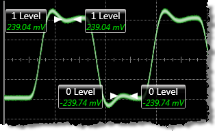
- Between the first two edges, the average value of the portion of the waveform spanning the center 20% is determined.
- Between the second and third edges, the average value of the portion of the waveform spanning the center 20% is determined.
- The absolute value of the difference between the two average values is the OMA measurement.
An estimation of OMA can be made using Eye mode's OMA at Crossing measurement, which is not based on specific NRZ patterns using consecutive ones and zeros.
This measurement is not compatible with PAM4 signals.
Configurable Measurement Parameters
This measurement is affected by the following settings (click Measure > Configure Base Measurements):
- Top-Base Definition tab
- Thresholds tab
To measure
- Select Oscilloscope Mode.
- Click the toolbar's Amplitude tab.
- Click the toolbar's More buttons to locate the Optical Modulation button.
- Click the button.
- If measurement regions are enabled, the Select Measurement Region, Setting dialog is displayed. Select the area over which the measurement is to be performed: a Region or the Entire Display.
Set the time span to display at least three edges on the screen. If less that three edges are shown, the error message "Edge?" is displayed. The three edges do not need to be equidistant, but they must contain enough samples to provide meaningful data. Therefore, it is best to set the span so that the three edges cover as much of the display as possible.
SCPI Command
:MEASure:OSCilloscope:OMAmplitude