RMS

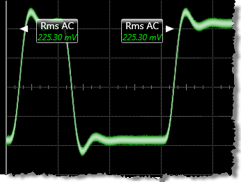 The Oscilloscope mode RMS is a measure of the AC or DC RMS of a pulse waveform. This measurement is compatible with PAM4 signals over the entire display or region but not over a cycle. An annotation label is placed at the RMS result. The positions of the labels are dependent upon the configuration of the RMS measurement. You can configure the measurement to be made across the entire waveform display, a measurement region, or across one cycle of the waveform.
The DC RMS measurement is the typical method of making an rms voltage measurement. This measurement is determined as followed:
where:
n is the number of waveform points on screen and not the memory depth and v(i) is the voltage at the i th point on screen.
The AC RMS measurement is a modified rms measurement. It removes the DC component of the waveform from the calculation of the rms voltage. This measurement is determined as followed:
where:
n is the number of waveform points on screen and not the memory depth and v(i) is the voltage at the i th point on screen.
This command is PAM4 compatible when it is made over the display or a region. It is not PAM4 compatible when made over a cycle.
Configurable Measurement Parameters
This measurement is affected by the following settings (click Measure > Configure Base Measurements):
- Top-Base Definition tab
- Thresholds tab
To measure
- Select Oscilloscope Mode.
- Click the toolbar's Amplitude tab.
- Click the toolbar's More buttons to locate the Rise Time button.
- Click the button and, if measurement regions are enabled, select the area over which the measurement is to be performed: a Region or the Entire Display.
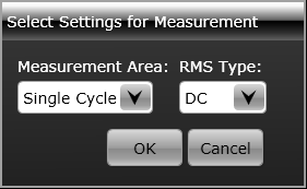
- Select the Measurement Area (Single Cycle or Entire Display/Region) and RMS Type (DC or AC).
- Click OK.
SCPI Command
:MEASure:OSCilloscope:VRMS