This S9x571B application allows you to configure two VNA sets (PXI or Streamline) separated by up to 5 meters. This capability enables long‑distance S‑parameter measurements, such as cable testing and antenna characterization, while providing improved dynamic range and measurement stability.
Supported Model
M980xA (M9834A/M9837A are not supported)
P50xxB/M (P93xxB is not supported)
S9x551B Multiple instruments/modules measurements is also required.
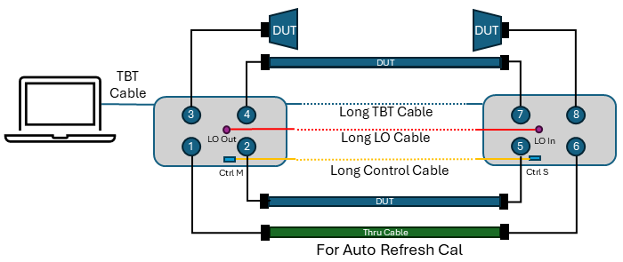
The Distributed VNA requires one reciprocal thru cable to make the Auto refresh Cal. The thru cable must be connected during measurements.
The DUTs can be connected on the other ports. The figure shows an example of Streamline VNA.configuration. If phase measurement is not required, The thru cable for Auto Refresh Cal is not necessary.
When your DUT is a thru cable, the cable for auto refresh calibration (ports 1 to 6 in this example) can be a DUT. In that case, the path for auto refresh cal must be connected during the measurements. Otherwise, "Auto Refresh cal is inactive" will be displayed.
Two units of Strealeamline VNA can be configured as shown in the figure above.
The required accessories are:
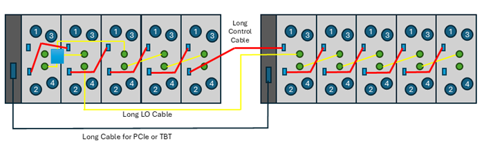
The limitation of PXI configuration are:
Two chassis only
Up to five modules in one chassis (Total 10 module)
6 port x M980xA: Up to 60 ports
The following two configurations are supported.
M9038A (Chassis1, Slot1) TBT Cable to M9025A (Chassis2, slot1)
Host Desktop PC with SP0630A – SP0633A PCIe Cable –SP0631A PCIe (Chassis1, Slot1) – Y1730A-520 PCIe Cable – SP0631A PCIe (Chassis2, slot1)
Please refer to configuration guide for the required components.
The following figure shows the configuration using PCIe Cable connection with an external host PC.
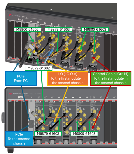
Power on the two modules or chassis after configuration is completed (LO cables and control cables must be connected before power on)
Launch the VNA application
Select the measurement class and setup your desired measurement setting.
To activate the distributed VNA feature
Click Setup > Internal Hardware > Distributed VNA, then Distributed VNA dialog box is displayed
Check Enable distributed VNA, then click OK.
Preset is done.
DistVNA is displayed in the status bar.
Set up your desired settings. Auto Refresh Cal has the following limitations. If phase measurement is not required, ignore this limitation because Auto Refresh Cal is unnecessary.
If the reciprocal thru is too lossy, measurement errors increase and Auto Refresh Cal may not function correctly. To minimize measurement errors, the following conditions are recommended:
Output Power ≧ -5 dBm
IFBW ≦ 100 kHz
Reciprocal thru cable loss < 20 dB
For M980xA, P500xB, P502xB, and P502xM (x = 5–8), meet these conditions from 500 kHz to 50 GHz.
If the reciprocal thru is too lossy, the following warning is displayed and no correction is applied. This warning also is displayed when a reciprocal thru cable is not connected.
"Auto Refresh Cal is inactive. Path Px-x is too lossy."
When using a reciprocal thru cable with loss exceeding 20 dB, this warning may appear but you can disable it by clearing the Check Path checkbox. However, do so with caution and compensate by tightening other measurement condition, such as increasing Output Power above −5 dBm, reducing IFBW below 100 kHz, and enabling Averaging (or increasing the averaging factor). For example, if the reciprocal thru loss is 30 dB (20 dB limit + 10 dB), increase Output Power by 10 dB to +5 dBm, or reduce IFBW by a factor of 10 Hz to 10 kHz, or increase the averaging count by a factor of 10 to 10 averages.
For M980xA, P500xB, P502xB, and P502xM (x = 5-8), measurement errors are large below 500 kHz and above 50 GHz. In these ranges, Auto Refresh Cal uses measurement values from other frequencies to perform the correction. Therefore, correction cannot be applied if the measurement range is entirely below 500 kHz or entirely above 50 GHz, because no usable in-range frequency points are available for the correction. Set Frequency Start to 50 GHz or below and Frequency Stop to 500 kHz or above. If these conditions are not met, the following warning is displayed and no correction is applied:
"Auto Refresh Cal is inactive. Frequency Range cannot be corrected."
If the calibration is executed while at a distance for two units, Number of Point should meet the criteria
If two VNA sets can be placed closely during the calibration, the calibration steps can be reduced. Hence, there are two cases for calibration.
The calibration step is as shown blow. Confirm if the number of points meets the required condition before the calibration.
Click Cal > Main > Smart Cal (or Cal > Main > Other Cals > ECal... for ECal)
Select the required calibration ports and options. Then,
Define the Connector, DUT gender and Cal Kit. Check the "Modify Cal Type". Then, click Next for the next dialog.
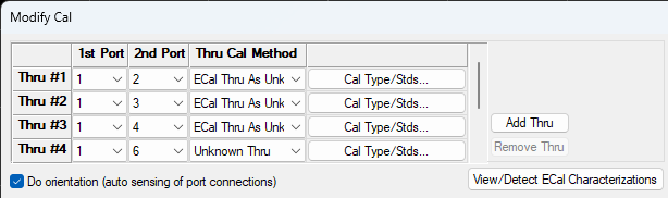
Define the 1st port and 2nd port for each thru.
Assign one port as a key 1st Port in the module (or Chassis) No.1. In the example below, port 1.
Assign each other ports in module No. 1 as 2nd port as "ECal Thru as Unknow thru" for Ecal, or "Unknown Thru" for mechanical cal kits.
Thru #1: 1-2
Thru #2: 1-3
Thru #3: 1-4
Assign one port in the module No.1 and one port in the module No.2 as Unknown Thru.
Thru #4: 1-6
Assign one port as a key 1st port in the module (or chassis) No.2. In the example below, port 5
Assign each other ports in module No. 2 as 2nd port as "ECal Thru as Unknown thru" for Ecal, or "Unknown Thru" for mechanical cal kits.
Thru#5: 5-6
Thru#6: 5-7
Thru#7: 5-8
Click Next for the next dialog.
Follow the instruction to execute the calibration.
Note: During the Thru measurement in step 4c (Thru #4: 1-6), do not move the long LO cable connecting the two modules.
Note: When using the ECal, a long USB cable is required to reach the remotely located VNA. A powered USB hub is also necessary to provide sufficient power to the ECal. Connect a long USB cable to the PC, with a powered USB hub at the other end, to which the ECal is connected.
Example 1: Streamline 8 port configuration. Ports 1 to 4 in the module No.1, ports 5 to 8 in the module No.2
Example 2: PXI 20 port configuration , Ports 1 to 10 in the chassis No.1, Ports 11 to 20 in the chassis No.2
|
|
1st Port |
2nd Port |
Thru Cal Method for Ecal |
Thru Cal Method for mechanical cal kits |
|
Thru #1 |
1 |
2 |
ECal Thru As Unknown Thru |
Unknown Thru |
|
Thru #2 |
1 |
3 |
ECal Thru As Unknown Thru |
Unknown Thru |
|
Thru #3 |
1 |
4 |
ECal Thru As Unknown Thru |
Unknown Thru |
|
Thru #4 |
1 |
5 |
ECal Thru As Unknown Thru |
Unknown Thru |
|
Thru #5 |
1 |
6 |
ECal Thru As Unknown Thru |
Unknown Thru |
|
Thru #6 |
1 |
7 |
ECal Thru As Unknown Thru |
Unknown Thru |
|
Thru #7 |
1 |
8 |
ECal Thru As Unknown Thru |
Unknown Thru |
|
Thru #8 |
1 |
9 |
ECal Thru As Unknown Thru |
Unknown Thru |
|
Thru #9 |
1 |
10 |
ECal Thru As Unknown Thru |
Unknown Thru |
|
Thru #10 |
1 |
11 |
Unknown Thru |
Unknown Thru |
|
Thru #11 |
11 |
12 |
ECal Thru As Unknown Thru |
Unknown Thru |
|
Thru #12 |
11 |
13 |
ECal Thru As Unknown Thru |
Unknown Thru |
|
Thru #13 |
11 |
14 |
ECal Thru As Unknown Thru |
Unknown Thru |
|
Thru #14 |
11 |
15 |
ECal Thru As Unknown Thru |
Unknown Thru |
|
Thru #15 |
11 |
16 |
ECal Thru As Unknown Thru |
Unknown Thru |
|
Thru #16 |
11 |
17 |
ECal Thru As Unknown Thru |
Unknown Thru |
|
Thru #17 |
11 |
18 |
ECal Thru As Unknown Thru |
Unknown Thru |
|
Thru #18 |
11 |
19 |
ECal Thru As Unknown Thru |
Unknown Thru |
|
Thru #19 |
11 |
20 |
ECal Thru As Unknown Thru |
Unknown Thru |
As this calibration uses a long thru cable, the unknown thru calibration requires larger number of points to determine the cable length.
Example Calculation
Frequency span = 50 GHz
hru cable length = 5 m
Cable type = polyethylene cable (Vf = 0.66)
Step 1: Calculate the maximum Δf
Δf < (0.66 × 2.997925E8 ) / (4×5)
Δf < 9.8 MHz
Step 2: Calculate the minimum number of points
number of points > (50 GHz / 9.8 MHz)+1
number of points >= 5103
Thus, at least 5103 points are required for the analyzer to automatically determine the Thru cable delay.
The maximum allowable frequency step (Δf) for automatic Thru cable delay estimation is determined using the following formula:
Δf<(V_f × c) / (2×l)
Where:
l = physical length of the Thru cable (meters)
Δf = frequency step size = span / (points − 1)
Vf = velocity factor of the Thru cable
c = speed of light = 2.997925 × 10⁸ m/s
A smaller Δf (i.e., more measurement points) enables the instrument to accurately determine the electrical delay of the Thru cable.
If the two VNA sets can be moved at the same place during calibration, there are the following benefits.
No requirement for Number of Points.(A short thru cable can be used)
Fewer calibration steps.
A powered USB hub and long USB cable are not required for ECal
The calibration steps are the same as Case 1, with the following difference:
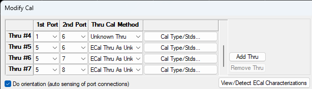
When assigning the cross-module thru (Thru #4: 1-6), select "ECal Thru as Unknown Thru" for ECal, or "Unknown Thru" for mechanical cal kits — the same as all other thru assignments.
Note: During the Thru measurement in step 4c (Thru #4: 1-6), do not move the long LO cable connecting the two modules.
Example 1: Streamline 8 port configuration. Ports 1 to 4 in the module No.1, ports 5 to 8 in the module No.2
|
|
1st Port |
2nd Port |
Thru Cal Method for Ecal |
Thru Cal Method for mechanical cal kits |
|
Thru #1 |
1 |
2 |
ECal Thru As Unknown Thru |
Unknown Thru |
|
Thru #2 |
1 |
3 |
ECal Thru As Unknown Thru |
Unknown Thru |
|
Thru #3 |
1 |
4 |
ECal Thru As Unknown Thru |
Unknown Thru |
|
Thru #4 |
1 |
6 |
ECal Thru As Unknown Thru |
Unknown Thru |
|
Thru #5 |
5 |
6 |
ECal Thru As Unknown Thru |
Unknown Thru |
|
Thru #6 |
5 |
7 |
ECal Thru As Unknown Thru |
Unknown Thru |
|
Thru #7 |
5 |
8 |
ECal Thru As Unknown Thru |
Unknown Thru |
Example 2: PXI 20 port configuration , Ports 1 to 10 in the chassis No.1, Ports 11 to 20 in the chassis No.2
|
|
1st Port |
2nd Port |
Thru Cal Method for Ecal |
Thru Cal Method for mechanical cal kits |
|
Thru #1 |
1 |
2 |
ECal Thru As Unknown Thru |
Unknown Thru |
|
Thru #2 |
1 |
3 |
ECal Thru As Unknown Thru |
Unknown Thru |
|
Thru #3 |
1 |
4 |
ECal Thru As Unknown Thru |
Unknown Thru |
|
Thru #4 |
1 |
5 |
ECal Thru As Unknown Thru |
Unknown Thru |
|
Thru #5 |
1 |
6 |
ECal Thru As Unknown Thru |
Unknown Thru |
|
Thru #6 |
1 |
7 |
ECal Thru As Unknown Thru |
Unknown Thru |
|
Thru #7 |
1 |
8 |
ECal Thru As Unknown Thru |
Unknown Thru |
|
Thru #8 |
1 |
9 |
ECal Thru As Unknown Thru |
Unknown Thru |
|
Thru #9 |
1 |
10 |
ECal Thru As Unknown Thru |
Unknown Thru |
|
Thru #10 |
1 |
11 |
ECal Thru As Unknown Thru |
Unknown Thru |
|
Thru #11 |
11 |
12 |
ECal Thru As Unknown Thru |
Unknown Thru |
|
Thru #12 |
11 |
13 |
ECal Thru As Unknown Thru |
Unknown Thru |
|
Thru #13 |
11 |
14 |
ECal Thru As Unknown Thru |
Unknown Thru |
|
Thru #14 |
11 |
15 |
ECal Thru As Unknown Thru |
Unknown Thru |
|
Thru #15 |
11 |
16 |
ECal Thru As Unknown Thru |
Unknown Thru |
|
Thru #16 |
11 |
17 |
ECal Thru As Unknown Thru |
Unknown Thru |
|
Thru #17 |
11 |
18 |
ECal Thru As Unknown Thru |
Unknown Thru |
|
Thru #18 |
11 |
19 |
ECal Thru As Unknown Thru |
Unknown Thru |
|
Thru #19 |
11 |
20 |
ECal Thru As Unknown Thru |
Unknown Thru |
Auto Refresh Cal compensates the phase drift of local signal due to a cable movement and temperature change.
Click Cal > Other Cals > Auto Refresh Cal...
Select the thru path for auto refresh cal.
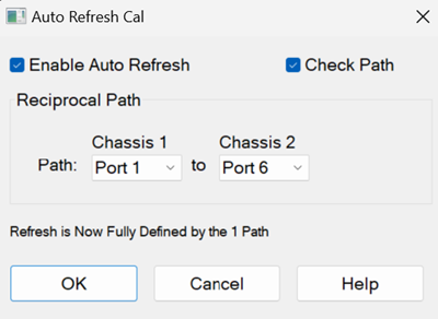
Check Enable Auto Refresh, then click OK.
Disable if Check Path function is not required.
ARefresh is displayed in the status bar.
Connect the DUT on the calibrated port and execute measurements
The thru cable for Auto Refresh Cal must be connected during the measurements.
"Refresh Cal is active" is displayed when the auto refresh cal works correctly
There is the following warning messages for Refresh Cal
Auto Refresh Cal is inactive. Path Px-x is not reciprocal.
Verify that a reciprocal thru is connected to path Px-x.
This warning can be disabled by unchecking “Check Path” or by “CALC:CORR:REFR:AUTO:CPAT:STAT”.
Auto Refresh Cal is inactive. Path Px-x is too lossy.
Verify that a thru is connected to path Px-x and that the thru cable does not have excessive loss.
This warning can be disabled by unchecking “Check Path” or by “CALC:CORR:REFR:AUTO:CPAT:STAT”.
Auto Refresh Cal is inactive. Frequency Range cannot be corrected.
Verify that there are measurement points within 500 kHz to 50 GHz.
Include at least part of 500 kHz to 50 GHz in the sweep range.
“Refresh Cal is active” is displayed when the above warning is cleared and Auto Refresh Cal works correctly
Supported Application and Feature
|
Model |
Description |
Supported |
|
S9x007A/B |
Yes |
|
|
S9x008B |
No |
|
|
S9x010A/B |
Yes |
|
|
S9x011B |
Yes (Advance Mode) See the limitation for TDR |
|
|
S9x015B |
No |
|
|
S9x024B |
No |
|
|
S9x025A/B |
No |
|
|
S9x027B |
Mechanical noise tuner control |
No |
|
S9x029A/B |
No |
|
|
S9x050B |
IQ data bandwidth up to 1.5 GHz |
No |
|
S9x051B |
IQ data bandwidth up to 4 GHz |
No |
|
S9x070B |
No |
|
|
S9x082A/B |
No |
|
|
S9x083A/B |
Vector & Scalar Mixer/Converter Measurements |
No |
|
S9x084A/B |
No |
|
|
S9x086A/B |
No |
|
|
S9x087B |
No |
|
|
S9x088B |
No |
|
|
S9x089B |
No |
|
|
S9x090A/B |
No |
|
|
S9x111B |
No |
|
|
S9x460B |
No |
|
|
Required |
||
|
S9x552B |
Multiport calibration assistant / Multiport ECal for PXI Switches |
No |
|
S9x553B |
No |
|
|
S9x560B |
N5252AWxx |
No |
The following features are not supported.