Mask Test Scaling
 Use the Mask Test Scaling dialog to specify how a mask is positioned and scaled against the eye diagram. Notice that the dialog's title identifies which of 16 possible masks is being scaled. You don't have to scale a mask every time a mask test is performed. Masks "track" the waveform, and as you change the waveform's vertical and horizontal scale or position, the mask moves with the waveform. If there is more than one eye diagram on the display, the mask is aligned to the first zero crossing point.
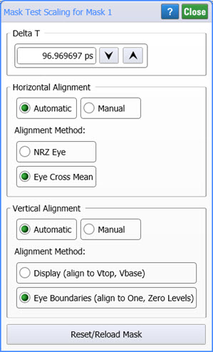
Changes made in this dialog modify the displayed mask, but do not alter the mask file. After changing the scaling in this dialog, you will no longer be using a standard mask and the Mask Test panel includes the notation "modified" next to the mask name. Click Reset/Reload Mask to re-apply the mask file thus removing any modifications.
Delta T
Delta T establishes the absolute shape of the mask width. Delta T is automatically set to the inverse of the symbol rate, which is the second eye-crossing time. This is true unless the value is specified in the mask file. Every standard mask has a predefined absolute width. These values can be specified in the mask file to any allowable time value.
Horizontal Alignment
Use the Horizontal Alignment field to position the mask along the graticule's horizontal axis. The mask can be automatically positioned relative to either the NRZ Eye or the Eye Cross Mean. NRZ Eye aligns the mask reference point to the first displayed eye crossing for NRZ measurements and is the default method. Eye Cross Mean aligns the mask reference point to the eye crossing mean of the rise and fall time at waveform average power at the first eye crossing point for NRZ eye measurements. Click Manual if you want to Position the mask to a specific time. If not specified in the mask file, Position is automatically set to the first eye crossing time.
Vertical Alignment
Use the Vertical Alignment field to position the mask along the graticule's vertical axis. The mask can be automatically positioned relative to either the Display, which is the eye's Vtop and Vbase values or to the Eye Boundaries, which is the eye's one and zero levels. The default method is to align to the Eye Boundaries. Click Manual if you want to position the mask to a specific value.
Each logic level moves independently of the other unless Logic Level Track is selected. When you enable logic level tracking, the logic levels are dependent upon each other, allowing you to manually move the mask up and down on the display. For example, if you adjust the logic 1 level by 5 mW, the logic 0 level will also move by 5 mW. When you disable logic level tracking, the logic levels can be moved independent of each other.
Generally, it is not recommended to align to the Display (Vtop , Vbase). Y-axis mask align does not apply to fixed-voltage masks.
When aligning a fixed voltage mask (for example, XAUI), only mask position is adjusted. The logic 1 and logic 0 levels remain unaffected.
Changing the mask parameters does not affect the waveform data on the display.