SNDR Result
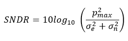
 For the output signal of a transmitter, the Signal-to-Noise-and-Distortion Ratio (SNDR) measurement compares a calculated ideal signal model to the measured signal. The measurement requires a specified pattern, so confirm that you are using the correct pattern before you perform this measurement. Settings that allow you to adjust the measurement's algorithm are found in the Jitter Mode Measurement Setup dialog's Amplitude Measurements tab. These settings include the measurement's linear pulse fit definition with the (P-Max or P-Signal), Sigma E (σe rms), and Sigma-N (σn rms) terms as shown in this equation.
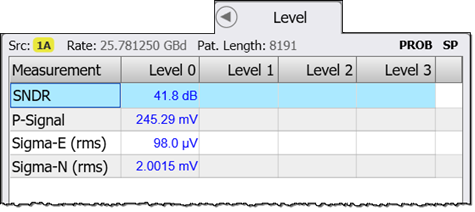
The measurement results are displayed in Jitter Mode's Level results panel as shown in the following figure. In addition to the SNDR measurement, three supporting measurements are also displayed. These include Sigma-E (rms), Sigma-N (rms), and either P-Max or P-Signal, which apply a different method for determining the amplitude of the ideal signal model. These values are helpful in gaining an understanding of the different components affecting the SNDR measurement.
SCPI Command
:MEASure:PLEVel:SNDRatio