RIN Results
 Click the Measurement (Meas) toolbar's RIN to activate Jitter mode's Relative Intensity Noise (RIN) measurement. This is the measurement of the noise-to-signal ratio of an optical source. Because this is a measurement specific to an optical signal, the Jitter Mode's Amplitude panel only lists the RIN measurement when the channel units are set to Watts.
To perform a RIN measurement
Use these steps to configure and run a RIN measurement on an NRZ signal that is based on the IEEE 802.3 algorithm. This procedure performs the following tasks:
- Performs the RIN measurement relative to the optical signal's OMA level.
- Normalizes RIN measurement to the sampling channel's equivalent noise bandwidth (optical reference filter turned on).
- Removes the module's intrinsic noise.
Procedure
- Click Tools > Calibrations > Calibrate and perform a module calibration. Module calibration characterizes the oscilloscope's noise.
- Click the Pattern Lock button which is located on FlexDCA's bottom tray.
- Click the desired Channel button that is located on FlexDCA's bottom tray. In the displayed Setup dialog:
- Select the Wavelength of the optical input signal.
- In the Reference Filter fields, select Filter On, and the baud rate that most closely matches a 53.125 GHz 4th order Bessel Thompson.
- Place FlexDCA in Jitter mode.
- Click Measure > Configure Jitter Mode Measurements to open the Jitter Mode Measurement Setup dialog.
- Click the dialog's Advanced tab.
- In the Random Jitter/Interference (RJ/RN) field, select the RJ/RN Compensation tab.
- For the RN Compensation, select Remove Scope Noise.
- In the dialog's Amplitude Measurements tab, select these settings:
- Set the RIN Relative To field to OMA.
- Set the Normalization field to dB/Hz.
- Set the Definition field to IEEE 802.3.
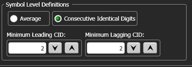
- Set the Symbol Level Definitions to Consecutive Identical Digits with a minimum of 3 Leading CID and 2 Lagging CID.
- Close the dialog.
- In the Meas toolbar (located along the display's left side), find and click the RIN measurement.
If a message error occurs, click Setup > Trigger Setup and in the Trigger Setup dialog select the Pattern Lock Setup tab. Select all of the Auto Detect check boxes and select the Clock Ratio setting.
To perform an IEEE standard 802.3 measurement, set RIN Relative To to OMA and Normalization to dB/Hz. These settings are not automatically made.
Performing a RIN measurement on an electrical channel
You can perform a RIN measurement on an optical signal that is input to an electrical channel by using an external O/E transducer. For this to work, you must setup the transducer with these steps. The RIN measurement will then be available and, if desired, you can also perform a dark calibration on the electrical channel.
To configure an external transducer
- Click the External HW button in the electrical channel's Channel setup dialog.
- In the Channel External Hardware Setup dialog, select An External Transducer is Connected.
- Click Setup.
- In the Transducer Conversion Factors dialog, select WATT for the units. Enter the transduce's gain and offset.
To configure an external transducer with SCPI commands
- Use the
:CHANnel:TRANsducer:STATecommand to specify that an external transducer is connected. - Use the
:CHANnel:TRANsducer:UNITscommand to selectWATTas the measurement units. - Use the
:CHANnel:TRANsducer:GAINand:CHANnel:TRANsducer:OFFSetcommands to specify the transduce's gain and offset.
Measurement Configuration
Use the following settings in the Jitter Mode Measurement Setup dialog's Amplitude Measurements tab to configure the measurement. Click Measure > Configure Jitter Measurements.
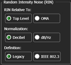
Relative Intensity Noise fields
RIN Relative To: RIN is measured relative to the Top Level or to the OMA. When Top Level is selected, the measurement is easier to compare with traditional measurements such as those done with a Keysight 71400C Lightwave Signal Analyzer. For NRZ signals, the Top Level is level one. For PAM4 signals, the Top Level is level three. When OMA is selected, the measurement is defined by IEEE 802.3ae. In addition to using 0000011111 patterns recommended in the standard, FlexDCA allows you to make RIN OMA measurements on the industry standard 2N-1 PRBS patterns. (To increase measurement speed, use a value of N that is less than or equal to 11.)
Normalization: If the input channel has an optical reference filter, the RIN value can be normalized to the equivalent noise bandwidth of the sampling channel by selecting dB/Hz. The dB/Hz selection is not available if the channel does not have a filter or the filter is not on.
Definition: Select results that are based either on FlexDCA's Legacy algorithm or the IEEE 802.3. The result of the IEEE based measurement is approximately 6 dB greater than FlexDCA's legacy measurement. Legacy is the default selection.
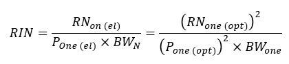
Legacy equation with RIN based on one level:
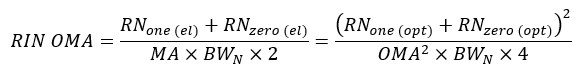
Legacy equation with RIN based on OMA:
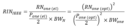
IEEE equation with RIN based on one level:
IEEE equation with RIN based on OMA:
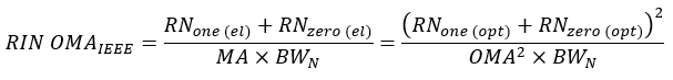
Where:
- RNone(el) is the electrical Random Noise power measured at the one level for NRZ signals. For PAM4 signals, level three (top level) is used. The RN measurement shown in the Amplitude panel is the noise equivalent power (NEP) in optical terms (RNone(opt)).
- RNzero(el) is the electrical Random Noise power measured at the zero level. The RN measurement shown in the Amplitude panel is the noise equivalent power (NEP) in optical terms (RNzero(opt)).
- Pone(el) is the electrical power of the one level caused by the optical power Pone(opt). For NRZ signals level one (top level) is used. For PAM4 signals, level three (top level) is used.
- BWN is the noise bandwidth of a 4th order Bessel-Thomson reference receiver. BWN = 1.05 x 3/4 x symbol rate.
- MA is the electrical power of the modulation amplitude caused by the Optical Modulation Amplitude (OMA).
RIN expressed in decibels is simply ten times the log of the results of the equation.
Symbol Level Definitions fields
It is recommended to choose at least two leading and two trailing Consecutive Identical Digits (CIDs) to avoid overshoot, ringing, and inter-symbol interference at the sample point where FlexDCA measures the random noise. If you enter too many CIDs, the instrument warns that it can not find such a sequence in the pattern.
SCPI Command
:MEASure:AMPLitude:RINoise