DFE Operator (Taps)
The Decision Feedback Equalizer (DFE) is a form of non-linear equalization which relies on decisions about the levels of previous symbols (high/low) to correct the current symbol. This allows the DFE to account for distortion in the current symbol that is caused by the previous symbols. Its main advantage over linear equalizers is the ability to cancel inter-symbol interference (ISI) without amplifying the noise. The DFE operator allows you to validate hardware DFE designs and observe their effects on eye openings.
The DFE's taps are applied to normalized 1/−1 voltages based on a symbol slicer decision. The tap values are meant to correct for the portion of their symbol that lingers and distorts the current symbol.
The Decision Feedback Equalizer operator is not available in TDR/TDT mode.
The Decision Feedback Equalizer operator requires a single-valued waveform, as opposed to an eye diagram. Be sure that your trigger setup results in a single-valued waveform at the input to this operator. This can be achieved using an external pattern trigger or by using pattern lock. If you are using an external pattern trigger, you may ignore this note.
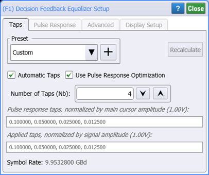
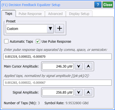
Click on the operator to open the Setup dialog with the Taps tab selected.
Automatic Taps
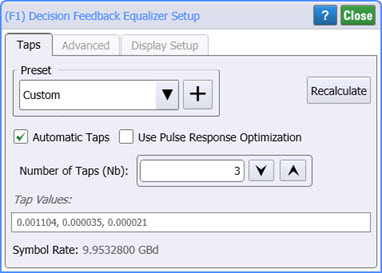
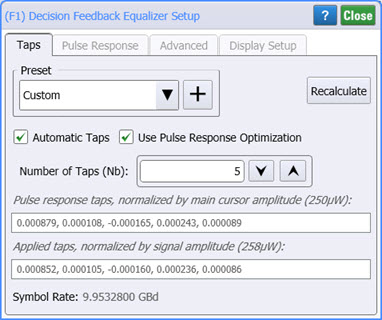
When Automatic Taps is selected, the tap values are automatically generated and viewed in the dimmed Tap Values field. You can specify the number of taps used from 1 to 16 taps. Click Recalculate anytime to regenerate the automatic taps based on the current input waveform.
If Use Pulse Response Optimization is selected, the following table shows which settings are available depending on the Automatic Taps and Use Pulse Response Optimization settings.
When Use Pulse Response Optimization, the dialog's Pulse Response tab appears. The tab is hidden when this selection is cleared.
| Optimization Settings | Dialog Tab | Gating Settings | |||
|---|---|---|---|---|---|
| Automated Taps Setting | Use Pulse Response Optimization | ||||
| OFF | ON | OFF | ON | ||
| Tap values entry field | Taps | ■ | ■ | ||
| Signal Amplitude | Taps | ■ | ■ | ||
| Main Cursor Amplitude | Taps | ■ | ■ | ||
| Tap Limits (bmax(N)) | Advanced | ■ | ■ | ■ | |
| Pulse Delay (Dp) | Pulse Response1 | ■ | ■ | ■ | |
| Pulse Length (Np) | Pulse Response1 | ■ | ■ | ■ | |
| Save Pulse Response After Optimize | Pulse Response1 | ■ | ■ | ||
This dialog tab appears when Use Pulse Response Optimization setting is selected.
| Auto Taps | Response Optimization | |
|---|---|---|
| Off | On | |
| On |
|
|
| Off |
|
|
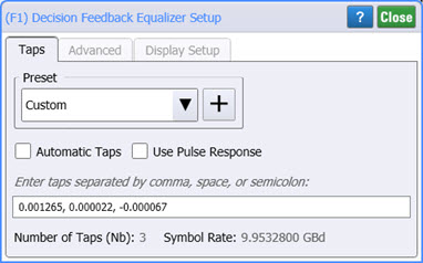
Manual Taps
To manually enter the tap values, clear Automatic Taps and enter your tap values. Separate each value using a comma, space, or semicolon. To determine the necessary number of taps, refer to the last section of this topic for a hardware DFE block diagram. If Use Pulse Response is selected, you can enter the values for:
- Main Cursor Amplitude. The applied taps are displayed and these taps are normalized by the signal amplitude, (pk-pk / 2)
- Signal Amplitude.
Before constructing your DFE, drag an output function color to your filter so that you can simultaneously view the input and output waveforms as you develop your equalizer.
Presets
Presets allow you to save your dialog settings to a setup file including any advanced settings. Recall a preset to instantly configure your Decision Feedback Equalizer to your specification. You can save as many presets as you need. If you scroll to the end of the list and click the <Edit List> entry, the Edit DFE Presets List dialog opens which allows you to reorder, delete, or rename items in the list.
- To save your settings, click the
 button.
 - To recall your settings, click Load.
| IEEE 802.3ck |
DFE and Jitter Mode
You can view the effects of the DFE in Eye mode or Jitter mode. Eye mode is meant to be more qualitative while Jitter mode has accurate quantitative amplitude measurements, including BER bathtub estimation. In Jitter Mode, amplitude graphs and amplitude scalar measurements (with the exception of BER measurements) can be made on the DFE operator's output waveform. However, jitter graphs and jitter scaler measurements are not compatible with the DFE operator. This is because the threshold transitions are placed at the symbol edges and such discontinuities make the jitter measurements invalid.
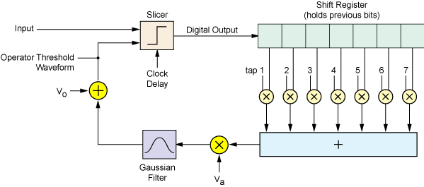
About Hardware DFEs
The DFE calculates a correction value that is added to the logical decision threshold. The logical decision threshold is the threshold above which the waveform is considered a logical high and below which the waveform is considered a logical low. As a result, the DFE shifts the threshold up or down so new logical decisions can be made on the waveform based on this new equalized threshold level.
Block Diagram of Hardware DFE
About The DFE Operator
To display the DFE's effect on an eye diagram, the DFE operator subtracts the correction factor from the input waveform and keeps the slicer threshold constant. The slicer results are equivalent to those of the hardware DFE.
Block Diagram of DFE Operator
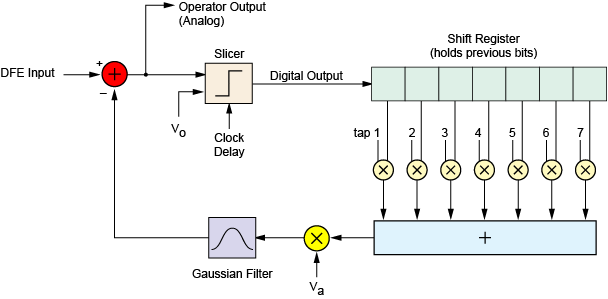
The DFE block diagram has the components:
- Slicer
- The slicer takes a clock delay, an offset voltage (Vo), and the input signal as its inputs. It places its decision point at the center of the symbol, and is then offset from there by the clock delay. Finally, it outputs ±1 based on whether the input voltage at the decision point is above or below the offset voltage.
- Vo
- This is the offset voltage of the input signal before it is corrected.
- Va
- This is the amplitude of the input signal.
- Gaussian Filter
- The Gaussian filter cutoff frequency defaults to the symbol rate but can be manually set up to 1 THz.
Tap Conversions From Other Systems
DFE taps from Keysight real-time scopes can be used directly. Taps from Advanced Design System (ADS) must be scaled by −1/Va (where Va is the input signal amplitude).