TDECQ
 The TDECQ (Transmitter and Dispersion Eye Closure Quaternary) measurement measures the quality of an optical transmitter with its optical link. TDECQ is the optical power penalty of the measured optical transmitter compared to an ideal transmitter. It measures the increase of optical power required for the measured optical transmitter to achieve the same eye opening as the ideal optical transmitter. The lower the TDECQ measurement, the higher the quality of the measured transmitter. TDECQ is a PAM4 replacement for an NRZ Transmission Dispersion Penalty measurement.
For compliance measurements on PAM4 or NRZ waveforms, use a Waveform Signal Processing TDECQ Equalizer operator.
The TDECQ measurement is not available when using simulated modules.
For NRZ waveforms, use the TDEC measurement. Note that the TDECQ Equalizer operator can be applied to both NRZ and PAM4 waveforms.
Requires pattern lock. Ensure that Acquire Entire Pattern is selected. This note applies to FlexDCA and not FlexDCA running FlexRT.
To perform a measurement on FlexDCA running in FlexRT
Refer to the FlexRT Quick Start.
To perform a measurement on FlexDCA
The following steps are the recommended technique for making a standards compliant measurement. You may gain additional measurement insights by changing settings such as the equalizer's tap values, but the resulting TDECQ measurement will not be compliant.
- Connect the PAM4 optical signal to an optical input channel.
- For FlexDCA and not FlexDCA running as FlexRT, perform these steps:
- Click Setup > Acquisition to open the Acquisition Setup dialog.
- In the dialog, click the Waveform tab.
- Click the Pattern Lock button to turn on pattern lock.
- Select Acquire Entire Pattern.
- In the Eye Generation field, select Wrap Waveform.
- Confirm that Enable Rapid Eye is turned off.
Select the Channel's Reference Filter
- Click the desired channel icon in the slot legend at the bottom of FlexDCA's window to open the channel Setup dialog.
- In the dialog, turn the channel on and in the Reference Filter field select Filter On. In the filter drop-down list, select the filter according to the following data rates:
- For a 26.56 Gbd signal (19.34 GHz BW specified in standard), select the 25.78 GHz filter (NRZ) or the 13 GHz filter (PAM4).
- For a 53.1235 Gbd signal use an N1092A (option IRC).
Compliance Measurements
- For compliance measurements, create a TDECQ Equalizer using the Waveform Signal Processing Setup dialog.
Measure TDECQ
- In the Eye mode measurement toolbar, click the PAM tab and click the TDECQ button.
- In the Settings dialog, if more than one signal is available, select the signal.
Compliance Measurements
 When making compliant PAM4 TDECQ measurements in Eye Mode, add a TDECQ equalizer waveform signal processing operator. The TDECQ standard calls for the insertion of the TDECQ equalizer into the signal path. Noise preservation is built into the TDECQ operator. The steps required to configure the TDECQ equalizer and to run the measurement are included later in this topic. The TDECQ equalizer's noise preservation compensates for the filter function's side effect of reducing a signals noise for adjacent measurement points. Preserving noise causes the operator to quantify the noise on each point on the operator's input waveform and restore this noise on the corresponding data point on the output waveform. Although there is a Preserve Noise setting in the operator's setup dialog, it is permanently turned on and you cannot turn it off.
When the TDECQ measurement is started, the measurement runs the equalizer's Automatic Taps feature. This determines equalizer tap values which result in the most evenly distributed eyes (levels). These are the "starting point" tap values for the equalizer's Iterative Optimization routine. The measurement continues based on the measured symbol Error Ratio (SER):
- If the SER value is smaller than the target SER value, Iterative Optimization is performed and the TDECQ measurement is made.
- If the SER value is larger than the target SER value and Optimize Histogram Times is on,
SER?is reported and Iterative Optimization is not performed. - If the SER value is larger than the target SER value and Optimize Histogram Times is off, Iterative Optimization is attempted and the TDECQ measurement is made, if possible.
When making TDECQ compliance measurements, a reference receiver 25 GBd filter is needed which the following modules provide N1092A/B/C/D/E Option 168 (25 GBd filter).
Additional Insights
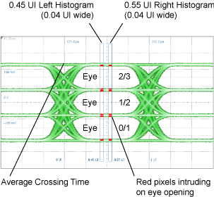
The TDECQ measurement uses two vertical histograms when performing the measurement. The histograms are annotated on the displayed waveform and are located at 0.45 UI and 0.55 UI from the waveform's average crossing time. This is shown in the following figure. The red pixels areas on the top and bottom eye edges highlight the areas that contribute the most to poor TDECQ results. The more equally spaced the red pixel areas are, the more distributed the errors.
TDECQ is unsuitable for a system-level test because the measurement is performed at an optical transmitter's output and because the there is an expectation that TDECQ remain constant if overall optical power and OMA is reduced in a linear method. This differs from Noise Margin which is made at the output of an O/E receiver and is a system-level test. Noise margin measures the amount of noise power that can be added to a system while maintaining its performance at a specific Symbol Error Ratio (SER).
Configure Base Measurements Settings
The TDECQ measurement is affected by the settings that are located in the TDECQ Configuration tab of the PAM-N Analysis Setup dialog (click Measure > Configure Base Measurements). This includes the ability to select optimization of the amplitude of decision thresholds within a specified percentage of the signal OMA, such that TDECQ is minimized. The timing of the histograms can also be optimized.
Complementary Measurements
Because TDECQ is a complicated measurement, there are four complementary measurements that are designed to measure the contribution to TDECQ of specific portions of the PAM4 waveform. These are the four measurements:
- Noise Margin (rms) used to perform a system-level test that is similar to TDECQ.
- Partial SER used to inspect contributing sources of target Symbol Error Ratio (SER) for TDECQ.
- Partial TDECQ used to inspect contributing sources of TDECQ.
- Partial Noise Margin used to inspect contributing Noise Margin sources.
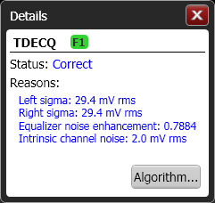
You can also click the Details button that is shown in the Results panel for supplemental measurement information as shown in the following picture. This information can also be returned programmatically by using the :MEASure:EYE:TDEQ:STATus:DETails? query. A "SER?" invalid status is reported when OMA fails to find a run of 6 zeros and 7 ones and that the target SER is lower than the actual.