PAM-N Setup (TDECQ Config tab)
TDECQ Configuration
 Use the TDECQ Configuration tab of the PAM-N Analysis Setup dialog to define the TDECQ measurement algorithm. Any setting that you make in the TDECQ Configuration tab, is also automatically changed in the dialog tabs listed in the following table. These settings are linked.
| Button | Feature | Linked Dialog Settings |
|---|---|---|
|
|
Eye Mode PAM Measurement Configuration |
PAM-N Analysis Setup dialog's TDECQ Configuration tab. |

|
Signal Processing Operators |
TDECQ Reference Equalizer Setup dialog's TDECQ Operator (Measurement). |

|
Reference Receiver Setup dialog's TDECQ Secondary Operator (Measurement). |
The TDECQ measurement settings in this dialog tab are the same settings found in the TDECQ Reference Equalizer Setup dialog's TDECQ Measurement tab. Change a setting in one of these dialogs and the setting is changed in both places.
Presets
Presets allow you to save settings in the TDECQ Configuration tab to a setup file. Recall a preset to instantly configure your TDECQ equalizer to your specification for standard TDECQ and CER TDECQ measurements. You can save as many presets as you need. The Preset list shows all of the factory provided presets as well as any that you have created. If you scroll to the end of the list and click the <Edit List> entry, the Edit TDECQ Presets List dialog opens which allows you to reorder, delete, or rename items in the list.
TDECQ Measurement Presets
- IEEE 802.3bs Amended
- IEEE 802.3bs
- IEEE 802.3cd
- IEEE 802.3db
- IEEE 802.3dj Draft 2.0 DR (500m)
- IEEE 802.3dj Draft 2.0 FR4 (500m)
- IEEE 802.3dj Draft 2.0 DR (2km)
- IEEE 802.3dj Draft 2.0 FR4 (2km)
- IEEE 802.3dj Draft 2.0 LR4 (10km)
- CEI-112G-Linear
- Fiber Channel PI - 7 Rev 0.13
- Open Eye - VEC Statistical 2.0
- Open Eye - VEC Statistical 3.0
CER Codeword Presets
- IEEE 802.3dj Inner FEC
- IEEE 802.3dj Outer FEC
Target SER
The Target SER sets the Target SER (Symbol Error Ratio) at which to perform the Eye mode TDECQ measurement. The optical power penalty of the measured optical transmitter is based on the amount of noise that would need to be added to obtain a target SER. This value can range from 1.0 x 10⁻¹² to 1.0 x 10⁻¹. The default setting is 4.8 x 10⁻⁴ SER, which is called out for 100GBASE-SR4 which uses FEC.
Histogram Properties
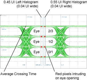
The Histogram Width setting configures the width of the two measurement histograms in UI (Unit Intervals). The Optimize Histogram Times setting is selected by default and it allows you to adjust Histogram Spacing which is the time separation in UI between the left and the right measurement histogram windows.
If you clear Optimize Histogram Times setting as shown in the following picture, you can individually position of the left and right histograms.
| Setting | Range | Default Value |
|---|---|---|
| Histogram Width | 0.01 to 0.10 UI | 0.04 UI |
| Left Histogram Position | 0.25 to 0.50 UI | 0.45 UI |
| Right Histogram Position | 0.50 to 0.75 UI | 0.55 UI |
| Histogram Spacing | 0 to 0.25 UI | 0.10 UI |
Threshold Optimization
Threshold optimization moves the thresholds from the standard definition by at most the percent of Outer OMA specified in the Adjustment Limit selection. The Adjustment Limit can be set from 0.1% to 100% with the default value being 1%. Select Enable to apply the limit.
OMA/ER Definition (PAM4)
The Minimum Zero Level Run and the Minimum Three Level Run settings enter the minimum number of consecutive UIs that must be present in the waveform. The runs can range from 5 to 1024 UIs. If the runs are shorter, the measurement is marked a questionable (a "?" character annotates the measurement's results).
The settings in this tab do not affect PAM4 measurements in Oscilloscope mode.