<Vertex> Element
The contents of the <Vertex> element defines one vertex of a polygon region. You need an element to define each vertex of your polygon. For example, drawing a hexagon requires six <Vertex> elements. You must list your vertices in clockwise or counter-clockwise order around the polygon's shape starting at any vertex. Listing vertices in a random order results in an invalid mask file.
Contents
The content of this element consists of two comma-separated numbers. The first number is the vertex's X coordinate. The second number is the vertex's Y coordinate. The vertex values are normalized to simplify using the masks for different symbol rates and logic levels. For example, if you halve the period of the waveform, you need only adjust the ΔX value to set up the mask for the new waveform.
X Value
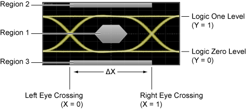
The vertex's X value represents the vertex's position as a ratio of the ΔX distance measured from the X scaling position. Unless the <MaskX1> element is used, the X scaling position is located at the eye diagram's first crossing point. The <DataRate> element establishes the ΔX time which is the span between the crossing points. For example, an X vertex value of 0.5 would position the vertex half of the ΔX time from the X scaling position.
Tvertex = (Xvertex × TΔX) + TX
Where:
- Tvertex equals the time at the vertex.
- Xvertex is the vertex's horizontal position as a ratio of the ΔX time measured from the X scaling position.
- TX is the X scaling position in seconds.
- TΔX is the ΔX time in seconds.
For example, if you set Xvertex to .100, TΔX to 100 ms, and TX to 100 ms, the time at the vertex (Vvertex) is 110 ms.
Y Value
The vertex's Y value represents the vertex's position expressed as a ratio of the difference between the logic 1 and logic 0 values. For example, a value of 0.5 would position the vertex midway between the logic levels. Specifying a vertex's Y value of 0 would place it at logic level 0. Specifying a vertex's Y value of 1 would place it at logic level 1. The following equation gives the relationship between logic levels, the vertex's Y value, and the voltage level at the vertex. The Y value can also be set to Infinity or –Infinity.
Vvertex = Yvertex (VY2 − VY1) + VY1
Where:
- Vvertex equals the voltage level at the vertex.
- Yvertex is the vertex's vertical position expressed as a ratio of the difference between the logic 1 and logic 0 values.
- VY2 is the logic 1 voltage.
- VY1 is the logic 0 voltage.
For example, if you set VY1 to 100 mV, VY2 to 1V, and Yvertex to 0.100, the voltage level at the vertex (Vvertex) is 190 mV.
Parent Elements
<Polygon>Child Elements
None.
Attributes
None.
Example
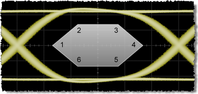
The following example creates the mask region shown in this picture. The vertex labels on this picture are provided for this example only and are not on the actual displayed mask. The comments in the following example code identify their associated vertex in the picture.
- <Region Number="1">
- <Polygon Type="Standard">
- <Vertex>0.22, 0.5</Vertex> <!-- vertex 1 -->
- <Vertex>0.375, 0.8</Vertex> <!-- vertex 2 -->
- <Vertex>0.625, 0.8</Vertex> <!-- vertex 3 -->
- <Vertex>0.78, 0.5</Vertex> <!-- vertex 4 -->
- <Vertex>0.625, 0.2</Vertex> <!-- vertex 5 -->
- <Vertex>0.375, 0.2</Vertex> <!-- vertex 6 -->
- </Polygon>
- </Region>
For Y values, the special value MIN automatically defines the bottom graticule, and MAX automatically defines the top graticule even when scaling is changed from the front panel or remote commands.