:FUNCtion:FOPerator
Command Syntax
:FUNCtion{1:64}:FOPerator  {NONE | ADD | ALIGn | AMPLify | AVALue | AVERage |
BESSel | BUTTerworth | CMODe | CNRZ5 | CONVolve | CTLequalizer | DCONvolve |
DDEConvolve | DDEMbed | DEConvolve | DELay | DEMBed | DFEQualizer | DIFFerence |
ENRZ | FFEQualizer | FFT | GAUSsian | INTegrate | INTerpolate | INVert |
MAX | MEDian | MIN | MULTiply | PEELing | PFIT | RANDom | RCOSine | RRX |
SINC | SQUare | SROot | SUBTract | SUMMation | TEQualizer |
VERSus | BUSer | USER}
Where the {1:64} specifier identifies one of sixty four math functions that you can create. For example, :FUNCtion2.
As of Revision A.04.00, the INTegrate argument has been deprecated. Use the SUMMation argument instead.
Query Syntax
:FUNCtion{1:64}:FOPerator?
Description
Installs a waveform signal-processing function which is identified by a number from 1 through 64. The command argument selects the type of operator. This topic includes a short description of each operator type with a link to the operator's main topic. Quick links in the above Command Syntax section link to content within this topic.
Function identification numbers are used to identify the function in setup and configuration commands. You do not need to assign consecutive numbers when creating a new function. For example, you can create function 5, function 8, and then function 2 as shown in the following lines:
:FUNCtion5:FOPerator ADD
:FUNCtion8:FOPerator INVert
:FUNCtion2:FOPerator AMPLify
Operators require FlexDCA revision A.05.00 and above.
Click on the following waveform signal processing icons to jump to function descriptions, and command argument, within this topic:
Math Functions


Simulation Functions


Signal Processing Functions


Transforms Functions
![]()
![]()
User/Custom Functions


Example Command Sequence
:FUNCtion2:FOPerator CONVolve
:SPRocess2:CONVolve:FNAMe "C:\Users\<user_name>Documents\Keysight\FlexDCA\S-Parameter Data\DUT_4.s2p"
:FUNCtion2:COLor TCOLor4
:FUNCtion2:DISPlay ON
Child Commands
:STATus?queries the measurement status.:STATus:REASon?query to determine why a measurement failed.
NONE Argument
Uninstalls the selected function.
:FUNCtion2:FOPerator NONE
ADD Argument (Add Operator)
Creates an addition operator that adds source 1 to source 2, point by point, and places the result in the selected function waveform. When vertical scaling is set to Auto, FlexDCA automatically sets vertical scale and offset to display the entire function on the display. Any changes to vertical scale or offset to the source waveform are tracked. In Manual mode, you set the function's vertical scale and offset; tracking is disabled.
To install the operator
:FUNCtion2:FOPerator ADD
ALIGn Argument (Align Operator)
Creates an align operator that lines up two single-valued waveforms or eye diagrams. The ALIGn function is not compatible with Jitter mode.
To install the operator
:FUNCtion2:FOPerator ALIGn
Configure the operator with these :SPRocess subsystem commands
AMPLify Argument (Amplify Operator)
Creates an amplify operator that is a copy of the operand. The magnify function is a software magnify. No hardware settings are altered as a result of using this function. It is useful for scaling channels, another function, or memories. Use the :FUNCtion:CONSTant command to specify the amount of amplification applied with this function.
To install the operator
:FUNCtion2:FOPerator AMPLify
Configure the operator with these :SPRocess subsystem commands
AVALue Argument (Absolute Value Operator)
Creates a absolute value operator where, for each input value, the Absolute math operator obtains the absolute values, point by point, of the source and places the result in the function waveform. Requires FlexDCA revision A.02.00 and above.
To install the operator
:FUNCtion2:FOPerator AVALue
AVERage Argument (Average Operator)
Creates an average operator that computes the average value of each time bucket for the defined operand's waveform. The AVERage function is not compatible with Jitter mode.
To install the operator
:FUNCtion2:FOPerator AVERage
Configure the operator with these :SPRocess subsystem commands
BESSel Argument (Bessel Operator)
Creates a fourth-order bessel operator that is a linear low-pass filter. The Bessel operator requires a single-valued waveform, as opposed to an eye diagram. Be sure that your trigger setup results in a single-valued waveform at the input to this operator. This can be achieved using an external pattern trigger or by using pattern lock. If you are using an external pattern trigger, you may ignore this note.
To install the operator
:FUNCtion2:FOPerator BESSel
Configure the operator with these :SPRocess subsystem commands
BUTTerworth Argument (Butterworth Operator)
Creates a butterworth operator that is a low-pass filter. The Butterworth operator requires a single-valued waveform, as opposed to an eye diagram. Be sure that your trigger setup results in a single-valued waveform at the input to this operator. This can be acheived using an external pattern trigger or by using pattern lock. If you are using an external pattern trigger, you may ignore this note.
To install the operator
:FUNCtion2:FOPerator BUTTerworth
Configure the operator with these :SPRocess subsystem commands
CMODe Argument (Common Mode Operator)
Creates a Common Mode operator that adds two sources, point by point, divides the sum by two, and places the result in the function waveform. The Common Mode operator is not available in Jitter mode.
To install the operator
:FUNCtion2:FOPerator CMODe
CNRZ5 Argument (CNRZ5 Decode Operator)
Creates a CNRZ5 chord operator that decodes a CNRZ-5 coded signal. The operator takes the six encoded input signals (representing five bits of information) and outputs five decoded NRZ waveforms with each output representing one of the five output bits. With five bits/symbol, the shortest pattern length to show all possible bit combinations is 32 symbols long (25 symbols). To ensure proper decoding, the input waveforms must be aligned.
To install the operator
:FUNCtion2:FOPerator CNRZ5
Configure the operator with these :TIMebase subsystem commands
CONVolve Argument (Apply s2p Operator)
Creates an Apply S2P operator that defines a basic one-block model for a two-port device. Use this operator when you want to compensate for the loss of a channel element such as a cable or fixture. The convolution process used by this operator requires that the measurement circuit and the simulation circuit be linear and time-invariant (small-signal analysis requirements). This operator requires a single-valued waveform, as opposed to an eye diagram. Be sure that your trigger setup results in a single-valued waveform at the input to this operator. This can be acheived using an external pattern trigger or by using pattern lock. Jitter measurements can be made on the Apply S2P operator's output waveform. Requires FlexDCA revision A.01.60 and above.
To install the operator
:FUNCtion2:FOPerator CONVolve
Configure the operator with these :SPRocess subsystem commands
CTLE Argument (CTLE Operator)
Creates a continuous time linear equalizer (CTLE) operator that is a first-order transfer function defined by DC gain, zero frequency, and two poles. If you are modeling equalization to open a severely closed eye diagram, you may need to manually set pattern lock on the instrument. Because the CTLE uses single-valued waveforms, it requires pattern lock triggering in either Eye/Mask or Oscilloscope modes. The convolution process used by this operator requires that the measurement circuit and the simulation circuit be linear and time-invariant (small-signal analysis requirements). This operator requires a single-valued waveform, as opposed to an eye diagram. Be sure that your trigger setup results in a single-valued waveform at the input to this operator. This can be acheived using an external pattern trigger or by using pattern lock. Jitter measurements can be made on the Apply S4P operator's output waveform.
To install the operator
:FUNCtion2:FOPerator CTLE
Configure the operator with these :SPRocess subsystem commands
DCONvolve Argument (Apply s4p Operator)
Specifies an Apply S4P operator to defines a basic one-block model for a four-port device. Use this operator when you want to compensate for the loss of a channel element such as a cable or fixture. The convolution process used by this operator requires that the measurement circuit and the simulation circuit be linear and time-invariant (small-signal analysis requirements). This operator requires a single-valued waveform, as opposed to an eye diagram. Be sure that your trigger setup results in a single-valued waveform at the input to this operator. This can be achieved using an external pattern trigger or by using pattern lock.
To install the operator
:FUNCtion2:FOPerator DCONvolve
Configure the operator with these :SPRocess subsystem commands
DDEConvolve Argument (Remove s4p Operator)
Specifies a Remove S4P operator that removes the effects of a four-port element from your measurements. This operator is easier to set up than the DeEmbedding operator (DDEMbed), however the measurement accuracy is reduced. Before you can use this operator, you must create an S-parameter file of the device to be removed. Jitter measurements can be made on the Remove S4P operator's output waveform.
To install the operator
:FUNCtion2:FOPerator DDEConvolve
Configure the operator with these :SPRocess subsystem commands
DDEMbed Argument (4-Port DeEmbedding Operator)
Creates a 4-port DeEmbedding operator that provides the most precision for removing or inserting test-setup elements. This operator creates a network that describes the full system of transmitter, receiver, and channel blocks. Using remote commands, you can open an existing network file that you have previously created and saved for your test setup and you can configure bandwidth settings. However, you cannot create and define networks using remote commands. Instead, create your network files using FlexDCA's menus. The convolution process used by DEMBed requires that the measurement circuit and the simulation circuit be linear and time-invariant (small-signal analysis requirements). This operator requires a single-valued waveform, as opposed to an eye diagram. Be sure that your trigger setup results in a single-valued waveform at the input to this operator. This can be achieved using an external pattern trigger or by using pattern lock. Jitter measurements can be made on the DEMBed's output waveform.
To install the operator
:FUNCtion2:FOPerator DDEMbed
Configure the operator with these :SPRocess subsystem commands
DEConvolve Argument (Remove s2p Operator)
Creates a Remove S2P operator that removes the effects of a two-port element from your measurements. is operator is easier to set up than the DeEmbedding operator (DEMBed), however the measurement accuracy is reduced. Before you can use this operator, you must create an S-parameter file of the device to be removed. The convolution process used by this operator requires that the measurement circuit and the simulation circuit be linear and time-invariant (small-signal analysis requirements). This operator requires a single-valued waveform, as opposed to an eye diagram. Be sure that your trigger setup results in a single-valued waveform at the input to this operator. This can be acheived using an external pattern trigger or by using pattern lock. Jitter measurements can be made on the Remove S2P operator's output waveform.
To install the operator
:FUNCtion2:FOPerator DEConvolve
Configure the operator with these :SPRocess subsystem commands
DELay Argument (Delay Operator)
Creates a Delay operator that applies a time delay to single-valued waveforms and eye diagrams. The DELay function is not compatible with Jitter mode. Requires FlexDCA revision A.01.60 and above.
To install the operator
:FUNCtion2:FOPerator DELay
Configure the operator with these :SPRocess subsystem commands
DEMBed Argument (2-Port DeEmbedding Operator)
Creates a 2-port DeEmbedding operator that provides the most precision for removing or inserting test-setup elements. This operator creates a network that describes the full system of transmitter, receiver, and channel blocks. Using remote commands, you can open an existing network file that you have previously created and saved for your test setup and you can configure bandwidth settings. However, you cannot create and define networks using remote commands. Instead, create your network files using FlexDCA's menus. The convolution process used by DEMBed requires that the measurement circuit and the simulation circuit be linear and time-invariant (small-signal analysis requirements). DEMBed requires a single-valued waveform, as opposed to an eye diagram. Be sure that your trigger setup results in a single-valued waveform at the input to this operator. This can be acheived using an external pattern trigger or by using pattern lock. Jitter measurements can be made on the DEMBed's output waveform.
To install the operator
:FUNCtion2:FOPerator DEMBed
Configure the operator with these :SPRocess subsystem commands
DFEQualizer Argument (DFE Operator)
Creates a Decision Feedback Equalizer (DFE) operator that is defined by waveform, taps, and target levels. If you are modeling equalization to open a severely closed eye diagram, you may need to manually set pattern lock on the instrument. Because the DFE uses single-valued waveforms, it requires pattern lock triggering in either Eye/Mask or Oscilloscope modes. Requires FlexDCA revision A.02.00 and above.
To install the operator
:FUNCtion2:FOPerator DFEQualizer
Configure the operator with these :FUNCtion:PATTern commands
Configure the operator with these :SPRocess subsystem commands
DIFFerence Argument (Difference Operator)
Creates a difference operator where the output is equal to x(n) − x(n−1). This function is designed for a single-valued waveform, as opposed to an eye diagram. The DIFFerence function is not compatible with Jitter mode.
To install the operator
:FUNCtion2:FOPerator DIFFerence
ENRZ Argument (ENRZ Decode Operator)
Creates a ENRZ chord operator that decodes an ENRZ coded signal. The operator takes the four encoded input signals (representing three bits of information) and outputs three decoded NRZ waveforms with each output representing one of the three output bits. With three bits/symbol, the shortest pattern length to show all possible bit combinations is 8 symbols long (23 symbols). To ensure proper decoding, the input waveforms must be aligned.
To install the operator
:FUNCtion2:FOPerator ENRZ
FFEQualizer Argument (Linear Equalizer Operator)
Creates a Linear Feedforward Equalizer operator (LFE) applies a finite digital impulse response (non-recursive) filter. The Linear Feedforward Equalizer operator requires a single-valued waveform, as opposed to an eye diagram. Be sure that your trigger setup results in a single-valued waveform at the input to this operator. This can be acheived using an external pattern trigger or by using pattern lock. Jitter measurements can be made on the Linear Feedforward Equalizer's output waveform.
To install the operator
:FUNCtion2:FOPerator FFEQualizer
Configure the operator with these :FUNCtion:PATTern commands
Configure the operator with these :SPRocess subsystem commands
FFT Argument (FFT Operator)
![]() Creates an Fast Fourier Transform (FFT) operator that takes the sample points of the waveform in the time domain and computes the frequency components. The FFT function is not compatible with Jitter mode.
Creates an Fast Fourier Transform (FFT) operator that takes the sample points of the waveform in the time domain and computes the frequency components. The FFT function is not compatible with Jitter mode.
To install the operator
:FUNCtion2:FOPerator FFT
Configure the operator with these :SPRocess subsystem commands
GAUSsian Argument (Gaussian Operator)
Creates a Gaussian operator that is a bandpass filter. The Gaussian operator requires a single-valued waveform, as opposed to an eye diagram. Be sure that your trigger setup results in a single-valued waveform at the input to this operator. This can be acheived using an external pattern trigger or by using pattern lock.
To install the operator
:FUNCtion2:FOPerator GAUSsian
Configure the operator with these :SPRocess subsystem commands
INTegrate Argument (Integrate Operator) (Deprecated Argument)
Deprecated argument. The short form of the argument (INTE) incorrectly specifies an INTerpolate operator. Use the SUMMation argument instead in FlexDCA revisions A.04.00 and above.
To install the operator
:FUNCtion2:FOPerator INTegrate
INTerpolate Argument (Interpolation Operator)
Creates an interpolation operator that adds new points between each of the input waveform's points and can be used to reconstruct a band-limited signal. The Interpolation operator requires a single-valued waveform, as opposed to an eye diagram. Be sure that your trigger setup results in a single-valued waveform at the input to this operator. This can be acheived using an external pattern trigger or by using pattern lock. The INTerpolate function is not compatible with Jitter mode.
To install the operator
:FUNCtion2:FOPerator INTerpolate
Configure the operator with these :SPRocess subsystem commands
INVert Argument (Invert Operator)
Creates a invert operator that inverts the defined operand's waveform by multiplying by −1. Not available in Jitter mode.
To install the operator
:FUNCtion2:FOPerator INVert
MAX Argument (Maximum Operator)
Creates a maximum operator that computes the maximum value of the operand waveform in each time bucket. The MAX function is not compatible with Jitter mode.
To install the operator
:FUNCtion2:FOPerator MAX
MEDian Argument (Median Operator)
Creates a median operator that computes the median value of each time bucket for the defined operand's waveform. The MEDian function is not compatible with Jitter mode.
To install the operator
:FUNCtion2:FOPerator MEDian
Configure the operator with these :SPRocess subsystem commands
MIN Argument (Minimum Operator)
Creates a minimum operator that computes the minimum value of each time bucket for the defined operand's waveform. The MIN function is not compatible with Jitter mode.
To install the operator
:FUNCtion2:FOPerator MIN
MULTiply Argument (Multiply Operator)
Creates a multiply operator that multiplies source 1 by source 2, point by point, and places the result in the selected function waveform. When vertical scaling is set to Auto, the instrument automatically sets vertical scale and offset to display the entire function on the display. Any changes to vertical scale or offset to the source waveform are tracked. In Manual mode, you set the function's vertical scale and offset; tracking is disabled.
To install the operator
:FUNCtion2:FOPerator MULtiply
PEELing Argument (TDR Peeling Operator)
Creates a TDR Peeling operator which is a signal processing math function that removes unwanted effects from multiple reflections during TDR measurements. TDR peeling cannot be used on TDT responses, because the lack of reflections invalidates the algorithm. So, you could use it on an T11 or S11 response but not on a T21 or S21 response. The TDR Peeling operator requires a single-valued waveform, as opposed to an eye diagram. Be sure that your trigger setup results in a single-valued waveform at the input to this operator. This can be achieved using an external pattern trigger or by using pattern lock command (:TRIGger:PLOCk). The TDR Peeling operator is only available in TDR/TDT mode.
When a device has two or more impedance discontinuities, reflections from the second discontinuity reflect off the first discontinuity. This complex interaction of secondary reflections from the stimulus pulse compromises the measured impedance profile and decreases measurement performance. TDR peeling compensates for the complicated interaction between discontinuities. TDR peeling analyzes reflected signals at the source and deconvolves the time domain reflections to create an impedance profile of the device being tested.
You can apply TDR peeling to calibrated, TDR responses by applying the TDR peeling math function to the underlying individual responses. For differential and common stimulus, apply the TDR peeling to the differential or common-mode response trace.
If a problem occurs while using the TDR peeling math function, the waveform may no longer be visible on the display. Causes of this effect include noisy traces as well as opens and shorts in the test setup.
What are the limitations of peeling?
- TDR peeling requires a trace record length of 1024 points or less. Use the
:ACQuire:RLENgthcommand to change the record length. - TDR peeling does not account for frequency response losses (for example, PC board transmission lines are lossy devices). The sum of the waves that are incident on a node are assumed to be equivalent to those exiting the node.
- TDR peeling assumes a lossless transmission line (resistance of 0). Any actual resistance (which causes loss, even at DC) degrades the accuracy of peeling.
- Instrument performance is reduced, because the peeling algorithm requires a factorial number of calculations (forward and reverse reflections grow overtime). It is not recommended to peel multiple traces simultaneously.
- The initial impedance mismatch is the most accurate; as distance increases from initial impedance mismatch down the transmission line, the impedance accuracy decreases.
To install the operator
:FUNCtion2:FOPerator PEELing
PFIT Argument (Pulse Fit Operator)
Creates a Pulse Fit operator which can be used with NRZ or PAM4 input signals. The Pulse Fit operator models a system pulse response to a one Unit Interval (UI) wide pulse that has the same amplitude as the signal. The system response is similar to an impulse response. The operator is most useful in Oscilloscope Mode but also reveals valuable insight when used in Eye/Mask mode. Pulse Fit is defined in some standards such as IEEE 802.3ck.
When using the Pulse Fit operator use Pattern Lock (:FUNCtion:PATTern:MODE command) and turn on Acquire Entire Pattern (:ACQuire:EPATtern command). Acquire entire pattern is not required but is recommended. Pulse Fit determines the pulse response waveform from the characteristics of the pseudo-random input pattern which is treated as a series of pulses having different polarities and amplitudes. The pulse fit uses the entire pattern and the pulse response is modeled (repeats) at the repetition rate of the pattern. This allows signal processing (for example, CTLE and linear equalization) on the response waveform. For more information, refer to the Pulse Fit operator in the FlexDCA User's Guide Help.
To install the operator
:FUNCtion2:FOPerator PFIT
Configure the operator with these :FUNCtion:PATTern subsystem commands
Configure the operator with these :SPRocess subsystem commands
RANDom Argument (Random Operator)
Creates a random operator that add random jitter or noise to the simulated waveform. The RANDom function is not compatible with Jitter or TDR modes. The Raised Cosine operator requires a single-valued waveform, as opposed to an eye diagram. Be sure that your trigger setup results in a single-valued waveform at the input to this operator. This can be acheived using an external pattern trigger or by using pattern lock. If you are using an external pattern trigger, you may ignore this note.
To install the operator
:FUNCtion2:FOPerator RANDom
Configure the operator with these :SPRocess subsystem commands
RCOSine Argument (Raised Cosine Operator)
Specifies a raised cosine filter operator.
To install the operator
:FUNCtion2:FOPerator RCOSine
Configure the operator with these :SPRocess subsystem commands
RRX Argument (Reference Rx Operator)
Installs a Reference Rx operator. To install the Reference Rx operator, address the :FUNCtion:FOPerator command to an available function number with the RRX argument. For example, :FUNCtion2:FOPerator RRX.
This operator is unique in that it provides joint FFE and DFE equalizer optimization. Up to three equalizers can be added as secondary operators:
- A CTLE equalizer,
- Either a Linear or TDECQ equalizer, and
- A DFE equalizer.
By default, the CTLE secondary operator is not installed at the time of the Reference Rx operator's installation. But, the TDECQ and DFE secondary equalizers are installed. To install or remove any of the secondary equalizers, use the :FUNCtion:SOP
:FUNCtion1:SOPerator2 CTLequalizer
:FUNCtion1:SOPerator3 FFEQualizer
:FUNCtion1:SOPerator4 DFEQualizer
The above commands install the secondary equalizer operators but do not assign function numbers. These operators are fully functional and can be configured using the commands in these SCPI nodes as long as you address these commands to the Reference Rx operator:
:SPRocess:RRX:SPRocess:CTLequalizer:SPRocess:DFEQualizer:SPRocess:FFEQualizer:SPRocess:TEQualizer
However, without function numbers you cannot configure the secondary equalizer operators using commands in the :FUNCtion SCPI subsystem which means that you cannot assign a waveform to the secondary equalizer operators. If you want to view secondary equalizer output waveforms, automatically assign function numbers to all installed secondary functions using this command:
:SPRocess1:RRX:SIFunctions ON
If you want to programmatically determine what function numbers have been assigned to the secondary functions so that you can configure them, use the :FUNCtion:SECondary? queries. This is useful in cases where you have installed the Reference Rx along with additional operators. In this case, the Reference Rx operator may not be assigned F1 and the secondary operators may not be assigned the usual F2, F3, and F4.
:FUNCtion subsystem commands that configure an installed secondary equalizer operator Display Setup settings are addressed to the function number assigned to the secondary operator. The difference is illustrated here:
:FUNCtion2:FOPerator RRX // Create the operator
:FUNCtion2:SOPerator2 CTLequalizer  // Install inner CTLE secondary operator
:SPRocess2:RRX:SIFunctions ON // Assign and view secondary functions
:FUNCtion2:COLor TCOLor14  // Assign color to Reference Rx output waveform
:FUNCtion3:COLor TCOLor6  // Assign color to secondary CTLE output waveform
Commands to configure common settings between equalizers
Use the :SPRocess:RRX commands to configure Reference Rx settings that are unique to the entire Reference Rx operator or that concern settings that are common to two or more secondary equalizers. That is, changes settings with one command, and the settings will be configured the same in all the effected equalizers.
| Setting | Effects | SCPI Node |
|---|---|---|
| Presets for Reference Rx settings | Save or recall Reference Rx configuration. | :SPRocess:RRX:PRESets
|
| Aliased Noise Processing | CTLE and Linear (FFE and TDECQ) equalizers | :SPRocess:RRX:PNOise
|
| Pulse Response Optimization | Non-Linear DFE equalizer | :SPRocess:RRX:PROPtimize
|
| Reference Point used for TDECQ measurements | TDECQ measurements | :SPRocess:RRX:RPOint
|
| Recalculation of automatically generated taps | Joint optimization | :SPRocess:RRX:RECalculate
|
Additional information on command availability
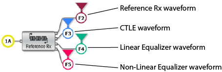
The following table lists the commands that you can use to configure the Reference Rx operator and their availability based on the Show Intermediate Functions setting that is located on the Reference Rx Setup dialog. The command examples in the table show the functions that you should address the commands to. For clarity, the colors used for the function address match the figure shown at the bottom of the table.
Just a few of the :FUNCtion subsystem are listed to illustrate the general pattern for these commands. For example, the :FUNCtion:COLor command setting is saved in a register and can be set on a secondary equalizer even if the Show Intermediate Functions is off, but the color will not be applied until Show Intermediate Functions is turned back on. Keep in mind that if Show Intermediate Functions is turned off and then turned back on again, you will have to reassign the functions to each installed secondary operator.
| SCPI Node or Command | Show Intermediate Functions ( :SPRocess:RRX:SIFunctions) |
Example of Valid Function ID Addressess | |
|---|---|---|---|
| ON | OFF | ||
:SPRocess:RRX
|
■ | ■ | :SPR1:RRX:PNOise
|
:SPRocess:CTLequalizer
|
■ | ■ | :SPR1:RRX:CTL:FZP
|
:SPRocess:DFEQualizer
|
■ | ■ | :SPR1:RRX:DFEQ:CLKDelay
|
:SPRocess:FFEQualizer
|
■ | ■ | :SPR1:RRX:FFEQ:DCGain
|
:SPRocess:TEQualizer
|
■ | ■ | :SPR1:RRX:TEQ:TAPS
|
:FUNCtion:SECondary?
|
■ | :FUNC1:SECondary?
|
|
:FUNCtion:SOPerator?
|
■ | ■ | :FUNC1:SOPerator?
|
:FUNCtion:COLor
|
■ | :FUNC1:COL
:FUNC2:COL
:FUNC3:COL
:FUNC4:COL
|
|
:FUNCtion:COLor
|
■ | :FUNC1:COL
|
|
|
|||
To install the operator
:FUNCtion2:FOPerator RRX
Example Command Sequence
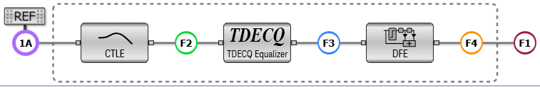
The following picture shows an installed Reference Rx operator that was created using the SCPI commands listed below.
:FUNCtion2:FOPerator RRX // Create the operator

:FUNCtion2:SOPerator2 CTLequalizer  // Assign inner CTLE secondary operator
:FUNCtion2:SOPerator3 FFEQualizer  // Assign inner Linear Equalizer secondary operator
:FUNCtion2:SOPerator4 DFEQualizer  // Assign inner Non-Linear Equalizer secondary operator

:FUNCtion2:COLor TCOLor14  // Assign colors and display function waveforms
:FUNCtion2:DISPlay ON
:FUNCtion3:COLor TCOLor6
:FUNCtion3:DISPlay ON
:FUNCtion4:COLor TCOLor4
:FUNCtion4:DISPlay ON
:FUNCtion5:COLor TCOLor5
:FUNCtion5:DISPlay ON

:SPRocess2:CTLequalizer:POLe2 1.700E+10
:SPRocess2:RRX:PNOise:BANDwidth:AUTo OFF
:SPRocess2:RRX:RPOint ASOP2
Configure the operator with these :SPRocess subsystem commands
SINC Argument (Sin(x)/x Operator)
Creates an Sin(x)/x, sinc(x), operator can be used to filter an input waveform. The sinc(x) operator requires a single-valued waveform, as opposed to an eye diagram. Be sure that your trigger setup results in a single-valued waveform at the input to this operator. This can be acheived using an external pattern trigger or by using pattern lock. If you are using an external pattern trigger, you may ignore this note. Jitter measurements can be made on the Sin(x) / x operator's output waveform. Requires FlexDCA revision A.02.00 and above.
To install the operator
:FUNCtion2:FOPerator SINC
Configure the operator with these :SPRocess subsystem commands
SQUare Argument (Square Operator)
Creates a square operator that takes the square of each value of each time bucket for the defined operand's waveform. Not available in Jitter mode.
To install the operator
:FUNCtion2:FOPerator SQUare
SROot Argument (Square Root Operator)
Creates a square-root operator where for each input value, point by point, the square root of the source is determined and placed in the function waveform. For example, a 10 mV input voltage point results in a 100 mV½; output point. The output units are not V or W. Instead, they are V½; or W½;, which are identified on screen as V½; or W½;. The scale of the output waveform does not track the input waveform. Requires FlexDCA revision A.02.00 and above.
To install the operator
:FUNCtion2:FOPerator SROot
SUBTract Argument (Subtract Operator)
Creates a subtract operator that algebraically subtracts the second operand from the first operand.
To install the operator
:FUNCtion2:FOPerator SUBTract
SUMMation Argument (Summation Operator)
Creates a summation operator that cumulatively sums the current and ALL previous (in time) input values. The summation operator requires a single-valued waveform, as opposed to an eye diagram. Be sure that your trigger setup results in a single-valued waveform at the input to this operator. This can be acheived using an external pattern trigger or by using pattern lock. If you are using an external pattern trigger, you may ignore this note. The SUMMation function is not compatible with Jitter mode.
To install the operator
:FUNCtion2:FOPerator SUMMation
TEQualizer Argument (TDECQ Equalizer Operator)
Creates a TDECQ equalizer. Normally, the TDECQ equalizer is automatically selected and used whenever a PAM4 TDECQ measurement is performed in Eye Mode. The equalizer is a five tap Finite Impulse Response (FIR) filter as described in the PAM4 standard. The TEQualizer function is not compatible with Jitter or TDR/TDT modes. Requires FlexDCA revision A.05.60 and above.
To install the operator
:FUNCtion2:FOPerator TEQualizer
Configure the operator with these :FUNCtion:PATTern commands
Configure the operator with these :SPRocess subsystem commands
VERSus Argument (Versus Operator)
![]() Creates a versus (X vs. Y) math operator that plots the source 1 amplitude on the vertical Y-axis and the source 2 amplitude on the horizontal X-axis. The VERSus function is not compatible with Jitter mode.
Creates a versus (X vs. Y) math operator that plots the source 1 amplitude on the vertical Y-axis and the source 2 amplitude on the horizontal X-axis. The VERSus function is not compatible with Jitter mode.
To install the operator
:FUNCtion2:FOPerator VERSus
USER Argument (User Operator)
Creates a one-input user operator that sends the input waveform to a Matlab or Python script and sends the output waveform from the script to the display. To configure your operator, use the :SPRocess:USER:CFILe command. Requires FlexDCA revision A.05.00 and above.
To install the operator
:FUNCtion2:FOPerator USER
Configure the operator with these :SPRocess subsystem commands
BUSer Argument (Two-Input User Operator)
Creates a two-input user operator that sends the input waveforms to a Matlab or Python script and sends the output waveform from the script to the display. To configure your operator, use the :SPRocess:BUSer:CFILe command.
To install the operator
:FUNCtion2:FOPerator BUSer